Member
Joined 2009
Paid Member
Foul!
That's glassware, Overnight Expert #1 and not a high current AB SS amp.

he he he he he
Well, I am now considering a doubler for an AB SS amp, we'll see how much I can get done this winter.
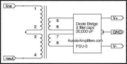
5th element: web sight ... is almost exactly there = spot on = full wave bridge, black capsules and everything.
For lower power amps, op-amps and pre-amps, add three healthy ferrite lugs in series on output rails (+, - and ground), just ahead of those fuses in the top schematic ... it takes that HF edge off enough so that persnickety amps that try to oscillate at the high end, don't.

For lower power amps, op-amps and pre-amps, add three healthy ferrite lugs in series on output rails (+, - and ground), just ahead of those fuses in the top schematic ... it takes that HF edge off enough so that persnickety amps that try to oscillate at the high end, don't.
Last edited:
Member
Joined 2009
Paid Member
Bigun: " I need a fair bit of current, ferrite won't cut it. I'm thinking capacitance multiplier. ..."
Increasing power passthrough by increasing capacitance is not a good answer. It always starts with the transformer. If you need more power (amps X voltage), you should pick the transformer that works and has the kohonies to suit.
The one I chose is rated above 900 VA so I felt justified in "derating" it to ~700 VA for the purposes of my "cooler running" amp modules (~350 watts each on +/0/- 77 VDC rails).
The ferrite "beads" I usually use are really ferrite lugs = massive puppies meant for #12 AWG wire or multiple stranded equivalent.
Last edited:
Member
Joined 2009
Paid Member
I don't doubt the bigger trafo is needed and I could soon whip off an order to digikey - but I have some junk to 'use up'. I have two hi-end Acopian linear power supplies each sporting 2 nice transformers, so 4 in total. I have 4 amplifiers I want to build. I also have around 10m of extruded Al heatsink (in 3m lengths) to use up. The heatink isn't really beefy enough for a juicy Class A but I think it can do the job at a low power level. This heatsink might be a good match to the Transformers which are rated at a lowly 25AC 5.5A.
It might seem a bit perverse limiting myself in this way given the time and effort that will go into designing and building an amplifier. But if I didn't impose some limits I'd have to go and build a fancy high power thing and I don't expect that to be nearly as much fun
You could say I'm more of a 'slowEddy' !
fastasulike: " ... single 24V secondaries, which is why I'm using four of them. ..."
Now THAT's a good way to do it! ... Benefits: each power rating X 4 = four times the power AND the "center tap" where you need it most.
([total] Volts times [total] Amps always equals Watts, totally ... That's the way God and Michael Faraday intended it to be.)
BYW: the logistics, how they get mounted, can also be tricky. Alignment of central cores of the transformers can either be complimentary, enhancing each transformer's performance, or not, creating extra hum and noise inside the box. Experimentation is suggested. The way each trannie gets connected to its neighbor(s) can either reduce heat generated or increase hum and RF noise.
Last edited:
Wiring to be one Txfmr per rail in a dual mono config via a bridge rectifier for each rail and two 10kuF caps in series, caps to be paralled across each rail pair, with the ground in the middle. An RF filter circuit immediately after this and then on to the amp modules. I'll be shielding each Txfmr in its own bay.
That's the simplified version anyway.
I'm not decided yet as to whether or not I need a soft start circuit, or just use a slow blow fuse.
That's the simplified version anyway.
I'm not decided yet as to whether or not I need a soft start circuit, or just use a slow blow fuse.
Last edited:
These are the modules......
http://i304.photobucket.com/albums/nn186/thewarpainter/ampmodules.jpg
http://i304.photobucket.com/albums/nn186/thewarpainter/ampmodules.jpg
Quad power amplifiers from the 606 on used a single winding to provide a split supply as shown in the attached schematic
http://www.dc-daylight.ltd.uk/Valve-Audio-Interest/Schematics/QUAD-606-service-data.pdf
This would allow you to use your transformers as intended
Stuart
http://www.dc-daylight.ltd.uk/Valve-Audio-Interest/Schematics/QUAD-606-service-data.pdf
This would allow you to use your transformers as intended
Stuart
405man: That is interesting ... the circuit establishes signal ground/ DC power ground (pseudo-center tap) with capacitors (AC side: C19, C18 + DC side: C12, C13 on the rectifier board).
I don't see any problems with this = a neat trick, and it must work just fine, as the amp power supply is in production as a "classic ... high quality" amplifier design.
A very good answer to the question, except for the extra circuitry and power for the transistors and voltage divider resistors, T15 and T16 on the amp board(s).
BTW: the amp in the original question is up and running with good results ... cool as a cucumber:
Last edited:
Yes no problem as long as they are similar transformers.
Well, there should be a common reference point if both 'formers are used to heat the same diode bridge / PS filters ... usually, on the secondary side for the common ground point (diagram at points "6" & "7" connected on the PS filter board.).

Temporary hookup and check with an AC voltmeter on both sides, primaries & secondaries, before you grab that soldering iron.
Last edited:
- Status
- This old topic is closed. If you want to reopen this topic, contact a moderator using the "Report Post" button.
- Home
- Amplifiers
- Power Supplies
- No center tap Help