Member
Joined 2009
Paid Member
Add me to the list of the baffled.
The transformer has dual primaries, and when paralleled they are used with 120VAC mains. There are two 55VAC secondaries. Unless I am having a senior episode, you therefore ALREADY have two 55VAC windings, and wiring the primaries in series (intended for 240v operation) and putting it across 120VAC will cut those in half. You would have, as noted by someone above, two 27.5VAC windings.
Those high current 55v windings will rectify and filter to the +/-75vDC that you want. One per polarity.
If you want to connect the two together to make a 110VAC CT (55-0-55), go ahead. I'd probably use separate bridges and make the two DC supplies, and reference each to ground with polarities opposing.
I don;t understand how the existing pair of 55VAC windings do not do exactly what you want when used as intended originally. AM I missing something?
Enzo: " ... dual primaries, paralleled, with 120VAC mains. There are two 55VAC secondaries. Unless I am having a senior episode, you therefore ALREADY have two 55VAC windings ..."
Well, yes, but. There is no center tap, so if the two secondaries are wired in series, and the central secondary connection used as a center tap ( 0 VAC), the voltage swings are ~ 110 VAC, top to bottom = through a standard diode bridge + caps = DC rail voltage of +155.5 / 0 / -155.5 VDC (1.414 X 110~).
I may take AussieAmplifiers.com advise and wire both sides in parallel (120 VAC into the primaries, 55 VAC out of the secondaries = +/0/- 77.7 VDC) and then connect the DC amplifier ground plane to the chassis ground (and house power ground) directly. (This may open the door for external noise and possible ground loops, but ...)
(The original QSC amplifier is/was a bi-polar transistor amp, so the two secondaries were used to obtain a source for regulated +/- 12 VDC for the pre-amp and +/0/- 155.5 VDC )
)
Clear as Cuervo? ... maybe its my turn to have that senior moment ... Maybe I'm totally wrong here, but my AC volt meter will know for sure.
Well, yes, but. There is no center tap, so if the two secondaries are wired in series, and the central secondary connection used as a center tap ( 0 VAC), the voltage swings are ~ 110 VAC, top to bottom = through a standard diode bridge + caps = DC rail voltage of +155.5 / 0 / -155.5 VDC (1.414 X 110~).
I may take AussieAmplifiers.com advise and wire both sides in parallel (120 VAC into the primaries, 55 VAC out of the secondaries = +/0/- 77.7 VDC) and then connect the DC amplifier ground plane to the chassis ground (and house power ground) directly. (This may open the door for external noise and possible ground loops, but ...)
(The original QSC amplifier is/was a bi-polar transistor amp, so the two secondaries were used to obtain a source for regulated +/- 12 VDC for the pre-amp and +/0/- 155.5 VDC
)Clear as Cuervo? ... maybe its my turn to have that senior moment
... Maybe I'm totally wrong here, but my AC volt meter will know for sure.
Last edited:
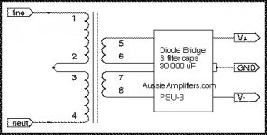
So basically you have this: http://tangentsoft.net/elec/tread/bitmaps/dual-supply.png, where 6 and 7 is your center. Unless I really slept in class...
There seems to be a lot of confusion over what exactly is in that QSC. The trafo has dual primaries (for 120/240 operation), and dual 110V secondaries (one for each channel). They do not have center taps because the QSC amp is one of those flying rail capacitively coupled amps. The supply generates +/-75V from 110VAC, and the ground floats with the audio singal. That topology requires completely isolated power supplies between channels. If you want a center tap you have to series the secondaries, and you get 110-0-110, not 55-0-55. To bring it down to the desired 55-0-55 you strap the primaries for 240 and put in 120.
Choices are: 1) strap the trafo as indicated, somewhat reducing the VA capacity, 2) Build an amp with a flying ground similar to the QSC - any transnova circuit and some normal amps can be made to do this, 3) Create a phantom ground with two huge rail caps and hope it's "good enough" for a normal amp topology, 4) ditch the trafo, or 5) rewind the trafo.
Choices are: 1) strap the trafo as indicated, somewhat reducing the VA capacity, 2) Build an amp with a flying ground similar to the QSC - any transnova circuit and some normal amps can be made to do this, 3) Create a phantom ground with two huge rail caps and hope it's "good enough" for a normal amp topology, 4) ditch the trafo, or 5) rewind the trafo.
wg_ski: " ... If you want a center tap you have to series the secondaries, and you get 110-0-110, not 55-0-55. [That's what I thought] "
" To bring it down to the desired 55-0-55 you strap the primaries for 240 and put in 120. ..." (Yes! parallel the primaries, cutting the input voltage in half and thus the output voltage in half, too, but making European operation difficult without inverters or ...).
wg_ski, thanks for making clear what I have made so cryptic. ... Now, off to the work bench. I believe I'll use choice # 1 (or #6) ... and connect signal ground + DC power ground plane <=> to the chassis ground at a single point with one of those ceramic disc thingies (the name escapes me at the moment)
=====
coolbeer: Thanks as well!
Exactly! ... plus a "restricted" connection from the 0 VDC / GND (signal / DC output ground) to the chassis ground. ( one of those ceramic disc thingies )
" To bring it down to the desired 55-0-55 you strap the primaries for 240 and put in 120. ..." (Yes! parallel the primaries, cutting the input voltage in half and thus the output voltage in half, too, but making European operation difficult without inverters or ...).
wg_ski, thanks for making clear what I have made so cryptic. ... Now, off to the work bench. I believe I'll use choice # 1 (or #6) ... and connect signal ground + DC power ground plane <=> to the chassis ground at a single point with one of those ceramic disc thingies (the name escapes me at the moment)
=====
coolbeer: Thanks as well!
An externally hosted image should be here but it was not working when we last tested it.
Exactly! ... plus a "restricted" connection from the 0 VDC / GND (signal / DC output ground) to the chassis ground. ( one of those ceramic disc thingies )
Last edited:

" Those primaries are still not in series. They need to be like this: ..."
NOT! ... unless you want the output to be +/0/- 155 VDC (from US/Canada 120 VAC power) ... I believe that would be about twice what I need for these: HPA-nxV500 550 Watt MOSFET Audio Amplifier Module ... I want the rails to be ~ +/0/- 75 to 78 VDC.
(Of course if MJL21193's circuit (above) were plugged directly into 240 VAC Euro-power, then = no problem-o.)
FYI: that QSC xformer is > 900 VA ... derating it to ~~ 800 VA for my purposes (without the fan) should do nicely ... since the AussieAmplifier.com stuff all runs much cooler than bi-polar transistor circuits for same power, same wattage ... well,
Last edited:
" Those primaries are still not in series. They need to be like this: ..."
NOT! ...
Whatever,
Another of those overnight expert thingies...
0-55 & 0-55Vac is just about right for 80-0-80Vdc.
You don't need to do anything special to change the transformer voltage.
If you parallel a pair of 110/120Vac primaries and connect them to a 110/120Vac supply them you will get the full AC current rating of the transformer. You will also get the designed output voltage from the secondaries.
If you series connect a pair of 110/120Vac primaries and connect them to a 110/120Vac supply you will reduce the total VA rating of the transformer to about half. It can output the same current but at half the voltage.
Similarly if you connect only one 110/120Vac primary to the 110/120Vac supply and leave the other primary disconnected you will get just half the input current, resulting in half the output current but at the correct voltage. Again about half the VA rating from the transformer.
Oops !!! ... My bad !!
MJL21193 ... YOU are right, I was WRONG !
Connecting the primaries in series is exactly what I should do to get the secondaries to the proper voltage = ~ 55 VAC, each secondary winding.
This is correct:

AndrewT: " 0-55 & 0-55Vac is just about right for 80-0-80Vdc. ..."
AND it is ! Oh joy ... I do really appreciate this blog. Upon arriving at the home shop (kitchen table), I hooked it all up as mjl suggests and = the ac voltmeter tells the tail = 54.4 VAC each ...
MJL21193 ... YOU are right, I was WRONG !
Connecting the primaries in series is exactly what I should do to get the secondaries to the proper voltage = ~ 55 VAC, each secondary winding.
This is correct:
AndrewT: " 0-55 & 0-55Vac is just about right for 80-0-80Vdc. ..."
AND it is ! Oh joy ... I do really appreciate this blog. Upon arriving at the home shop (kitchen table), I hooked it all up as mjl suggests and = the ac voltmeter tells the tail = 54.4 VAC each ...
Last edited:

FYI: that QSC xformer is > 900 VA ... derating it to ~~ 800 VA for my purposes (without the fan)
Halving the voltage essentially halves the power rating if copper loss dominates. That is the case for toroidal mains transformers.
However, if it is an EI or UI core transformer the big reduction in idle loss means that it will tolerate a little more than half the original rating. It could be up to 65% of the full-voltage VA rating if the original core-winding loss split was 50-50 (typical design value for a core-loss limited design).
Last edited:
Mmmmmm ... #14 AWG stranded primary wires (exterior), #16 AWG stranded secondary wires (exterior).
The circuit breaker is 10 amps @<250 VAC and a very healthy 15 to 18 pounds.
MegaJocke: I'm going to run with it, But I'll take your advise and watch for hot spots or a hot transformer, etc. ... before I let the band have at it.
The circuit breaker is 10 amps @<250 VAC and a very healthy 15 to 18 pounds.
MegaJocke: I'm going to run with it, But I'll take your advise and watch for hot spots or a hot transformer, etc. ... before I let the band have at it.
Last edited:
Member
Joined 2009
Paid Member
MJL21193 ... YOU are right, I was WRONG !
Careful, we don't want to make MJL21193 too comfortable !
Careful, we don't want to make MJL21193 too comfortable !
For those keeping score, that's MJL21193 - 2 points, Overnight Experts -0 points.
Member
Joined 2009
Paid Member
" ... 2 points, Overnight Experts -0 points ..."
From the top of the key!
Overnight Expert - 1 point
http://www.diyaudio.com/forums/tubes-valves/94890-greinacher-voltage-multiplier.html#post1116288
- Status
- This old topic is closed. If you want to reopen this topic, contact a moderator using the "Report Post" button.
- Home
- Amplifiers
- Power Supplies
- No center tap Help