I've checked the mosfets and the little 01k ground cap and they all seem fine I just need to check the mosfets. Does anyone know where on these the drain source and gate are. I'm looking at the shematic I think hafler uses a slightly different symbol for them i more confused now. I'm guessing the casing is drain? Or have i got it all wrong. Please explain in laymen's terms as I'm learning as i go
I think this amp has 2 completely different pre assembled modules the mosfet's aren't even the same brand. Do you think it's worth matching all the components up hopefully after its fixed. It sounded great before it broke.
I think this amp has 2 completely different pre assembled modules the mosfet's aren't even the same brand. Do you think it's worth matching all the components up hopefully after its fixed. It sounded great before it broke.
I found this on another thread by Dick West
looking at point number 7 it looks like my mosfets are brown bread!
There are so many possible variables it is difficult to give too much advice. But, here is a list of steps I might follow.
1. Get a Variac. You can pick up one with a 5 amp capacity off an eBay auction for around $50. It is an excellent investment for a POOGER.
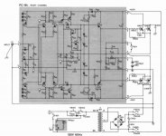
2. Study the schematic for the DH-200 and the DH-220. Learn the difference between NPN and PNP transistors. Also, learn the difference between N-channel and P-channel FETs (output MOSFETs).
3. Study the voltage chart in the DH-220 manual and get a feel for which points should have the same voltages in the DH-200 circuit.
4. MOSFETs are very rugged but I believe the 2SJ49s are more prone to failure than the 2SK134 devices. Did you perchance switch them around when you were messing with that channel?
5. Capacitor failure is frequent given the age of your amp. The two filter caps on the PCB probably should be replaced or at least the power supply rails voltages checked carefully.
6. You can measure many voltages on the bad channel AFTER removing the MOSFETs. This way there is less chance of a problem creating more problems. This is a circuit somewhat similar to an op-amp and feedback from the MOSFETs is required to keep some voltages settled and in spec, but at least you can get a ball park feel for how the circuit is operating.
7. You can check the viability of the suspect mica insulator with your VOM set to measure continuity. Obviously, there should be no continuity between the MOSFET case and the underlying heat sink.
8. What is the serial number of your amp? Which version of PCB does it have? Personally, I would not mess with the older phenolic PCBs. Their traces were glued on so too much soldering heat will dislodge them. Also, the driver transistors on the PCB (the ones with the small metal tops) may have cold soldered joints because the phenolic does not allow a hot enough solder bath in manufacture. If you have phenolic you should reflow all solder joints.
9. There are many voltage points to check but you can't do this if a MOSFET is overheating so you have a catch 22 except to remove the MOSFETs and do some sleuthing with the PCB by itself, with a Variac to carefully control voltage applied.
Good luck. . . BTW, I gave up POOGing 15 years ago. My favorite amp here has a pair of PCBs from Musical Concepts applied to a DH-200 chassis and transformer. The more recent PCB upgrades from Musical Concepts make for a stellar performer far superior to the the DH-200 or DH-220! If you have good soldering skills you can install the kit from MC.
My $0.02")
looking at point number 7 it looks like my mosfets are brown bread!
ok so it looks like I'm going to replace both 2SJ49's and it's still cheaper to order from the us. To stop this from happening again would anything have been damaged because these 2 mosfets are dead. I
If someone could confirm that the casing shorting to the frame is because the mosfets or dead or just the mica insulator. I checked them out and they seem ok. then i'll keep checking the rest on the pc19 board
If someone could confirm that the casing shorting to the frame is because the mosfets or dead or just the mica insulator. I checked them out and they seem ok. then i'll keep checking the rest on the pc19 board
Hello Simbl,
Third time lucky, I had typed about a pages worth, went back to look at your photos and lost the lot!, I'm not a happy chappy, webmaster take note. I should be able to reference relavant material, data sheets, images etc, without resetting my postings!
I agree with Dick West about the use of a Variac. I use a 1KVA variac on the load side of my series incandescent lamp rig which contains four paralelled, independently switchable 200w lamps. So the mains goes through my lamp rig, then the variac and on to the load under test. The lamps allow for the control of the source impedance (if you are unsure of what this is, look on wikipaedia!), and the variac allows for the control of the source voltage, so both Thevinin parameters are covered. (Again, look on Wikipaedia for "Thevinin's Theorem", it's a cornerstone of electronics.)
Now to the problem at hand, Simbl, you have found a fault by measurement, so the unit has answered one of your "questions", and this is your "foot in the door' to an "extended conversation" with this Haffler DH200. Don't get sidetracked bt slight differences in model numbers and other such irrelavant specifics, stay focused on the fault you have found.
Now, I cannot find my circuit at the moment, but I have gone and got my 'DH800', dusted it off, and have it here on a chair next to me. It is very tightly packed, unlike your rather open unit.
In mine one set of output devices face upwards near the lid, while the other set are down the bottom and nearly inacsessable without serious disassembly. In one channel, the 2SK176's are on top, while the 2SJ56's are underneath, and the opposite for the other channel. Luckely I hve managed to reach into the lower set of devices (output fets), through a convienently placed hole in the box with the multimeter probe. My unit has a speaker protector, (yours does not appear to have this, I cannot see it in your pictures). I have used a three phase motor contactor as the speaker protection relay, and, luckely, it is reachable with the multimeter.
Here is what I measured and deduced, (without the circuit, but it is still partly in my memory as I spent 8 months on the Haffler project 15 years ago). There should be a low impedance measurement, less than 0.2 ohms or so, between all the fet cans, (which are their source connection after looking at the datesheet, (by typing "2SK176" into Google)) and the hot side of the speaker protection relay, (or speaker hot speaker terminal for that respective channel if no protector is fitted). This is what I measured in my unit and you should get the same on your good channel.
Now, if one lot of cans are shorted to the heatsink, you have a problem. The other lot of cans should be shorted down too. In my high powered unit source terminal equalizing resistors are not used, all the source leads, device T0-3 cans, are simply comnnected to the speaker line.
If I recall, the lower power rated Hafflers possibly used source resistors although I cannot see them in your photographs. If there are any, there will be one in series with each source lead, i.e between the can of each output device and the speaker line. Eash resistor should be a low value, less than 0.5 ohms or so and have a power rating of at least 5 watts, so they will be relatively large compared to all the other resistors in the unit. If there arn't any, all cans will simply connect directly to the speaker node. To get from here to the hot side of the speaker terminals on the rear panel the signal usually passes through a Zobel Network and a protection relay, if fitted.
On the Haffler, one of the components of the Zobel Network is rather obvious, it is a coil of about 10 turns if 1mm dia. enameled transformer wire right in the middle of the board. The signal must pass through this to get from the sources of the output devices to the speaker terminals and it should be obvious on the circuit too. It is sometimes shunted by a resistor and almost always has a series resistor-capacitor network to ground on the output side. This is sometimes positioned right at the output terminals rather than on the board. the purpose of the Zobel Network is to prevent R.F. transmissions, such as A.M. broadcast radio picked up on long speaker leads acting as an antenna, from getting into the feedback path and causing the amplifier to burst into high frequency oscillation. Some Zobel Networks also have a series resistor-capacitor to ground on the input side as well but it is not always implemented by all manufacturers and I can't remember specifically what David Haffler did. To a multimeter, the Zobel coil should measure nearly zero ohms, so one should get this reading between the fet cans and the hot speaker terminal.
What seems rather odd is that you have measured a short from the cans of the K devices to the heatsink, but is there a corresponding short from the cans of the J devices also as their cans all connect to the same node? If true, this short should be measurable between the speaker terminals provided there is no speaker protection relay or damage to the Zobel Coil and its soldered connections. If you have removed the K devices from the unit and the short has cleared, then, either one of the washers under one of the K devices was damaged, one of the insulating bushes used on the mounting screws was likewise damaged, there is some other physical damage in the form of a metallic omic path from the device can to the heatsink and as such it is a hardware fault not an electronic one, or the driver transistor may be damaged. If the short has not cleared upon removal of the K devices, then the J devices mat be exhibiting a similar hardware fault. If the K devices were shorted down before removal, but the J devices wern't, then if source resistors are used some of them may be open circuit. Knowing if the hot speaker terminal was shorted down before removal of the K devices would have given maeningful imformation upon which sie source resistors may have gone open, those in the sources of the K devices or those in the sources of the J devices, assuming they are used at all.
If there are no source resistors, like my unit here, and one set of cans (K Devices) were shorted down but the J's not, then s very strange state of affairs exists and the speaker node has partly vaoprized!
Now to measure the fets, .....
Take a K device, it is an N-Channel device and fits into a circuit with its source "lead", the can, to the more negative parts and its drain lead to the more positive parts, the control is applied as a voltage between the source and gate leads.
Place the K device on the table in front of you with the two leads pointing upwards, turn it around so the shorter distance between the pair of leads and the mounting hole is on your side.
In this position the drain lead is on the lefthand side and the gate lead on the right.
Carefully place your thumb on the can, source connection, and then, while maintaining your thumb on the can, touch the gate, righthand, lead with one of your other fingers. This discharges the gate capacitance and turns the device off.
Set your multimeter to "continuity" or "diode" test. Place the black (neg) probe on the can, source, connection. Now touch the drain, lefthand, lead with the red (pos) probe. As the device is off, nothing should happen, the device should measure open circuit or very high impedance. (Be aware that some analog meters have the probe polarity reversed, use a modern digital multimeter such as a Fluke model).
Now, keeping the black probe on the can, touch the red probe to the gate lead, this charges the gate capacitance and turns the device on. Move the red probe from the gate to the source, you should get a 'beep" or whatever continuity indication your meter gives. Repeat the thumb and finger exercise to discharge the gate capacitance and turn the device off again. Repeat, black on can, red on left, no "beep", touch red to gate and then back to drain and "beep". Now, finally, reverse the meter leads, use the thumb and finger to discharge the gate capacitance again, put the red probe on the can, source, and the black probe to the lefthand lead, drain. You should now measure an internal diode. My meter beeps then stops and indicates 650mV in this case. 650mV is the foward bias of a silicon diode. Bear in mind your meter may give this indication in some other way. If the fet passes these tests there is a 95% chance it is undammaged, the remaining 5% indicating that it may have developed a "breakdown at voltage" fault where the drain leaks when more than 30v is applied to it. (If you have a small battery, 9-12v, and small globe, like one of those small automotive daslamps or radio dial lamp (use 6v lantern battery). Place the globe in series with the positive terminal of the battery, use the negative pole of the battery as the
"black lead of your tester" and the globe terminal remote from the one that goes to the positive pole of the battery as your "red tester lead" and repeat all the tests on the K device described above, the globe will turn on when the fet is on. With this setup permanently jigged to the fet, neg battery to can, drain to pos battery via globe, by placing your thumb or finger on the gate lead and touching the positive of the battery with any other part of your body, the globe should light up, touching the negative pole of the battery with any other part of your body (still while touching the gate lead of the fet), you should extinguish the globe. Rocking two fingers (of the opposite hand to the one touching the gate), between the two battery terminals, i.e. touching bot terminals at the same time with two fingers and pressing harder on one terminal while, at the same time pressing more lightly on the other battery terminal will adjust the voltage in your body and dim the globe up and down. (Do this final test only of the globe is quite small as this places the fet into its linear region and thus it will be effected by I squared R loss heating. Doing these tests should give you a good tactile feel for what a fet actually does.
If you wish to test a J device, P-Channel, do the same tests but with all polarities reversed, i.e. red-black mm leads or battery pos neg-terminals.
If the fet fails any of these tests, e.g. the gate capacitance does not charge up and the device does not come on, or it is shorted drain to source, and permanently on, then it is permanently stuffed and must be replace by a new one!
Now, from your photographs I notice that this amp has rail fuses, the pairs of 3AG fuse cartriges either side of the transformer, the other fuse on its own is most likely the mains fuse, so watch out, touching it while on with your other hand on the earthed box could be the last thing you do! As this amp is rated at around 200w per channel, 400w all up, and this type of circuit being about 60% efficient at delivering power from the mains lead to the speaker terminals when loaded (with 8 ohms), all up it will draw 400w plus the 40% loss in the transformer and output devices, which is 160 watts, then it should draw 560 watts from the mains when fully driven. In Britain, like Australia, I think the mains is 230 volts R.M.S. @ 50Hz. So a 1 amp fuse will allow a 230 watt load to be driven, any more and it will blow. So the mains fuse in your unit should be about 2-2.5 amp rated slow blow to take the magnetizing inrush of the transformer and filter cap chargeup at turn on. Check it, make sure some idiot previous owner has not put a 'nail' in there. Do no use automotive fuses, they are the ones with the flat ribbon elements inside which are sometimes thinner in the middle. Your mains fuse should have a spring inside along about two thirds its length. So, mains fuse, 2.5-3A slow Blow, (with spring inside).
Now to your rail fuses. My "Haffler" rail voltages are very high, something like +-85-90 volts, yours should be lower, something like +- 65 volts. So, to deliver 200 watts into 8 ohms, one must place 40 volts across it and thus 5 amps R.M.S flows in the speaker circuit. That is an R.M.S A.C. voltage with a peak value of root 2 (1.414) x 40 or 56v. So your amp must possess D.C. rail voltages of at least +-56v in order to deliver 200w of power to a 8 ohm load. The current which flows in each set of fets, alternately, is about 0.6-0.7 (for class AB operation and just more than half the cycle) times this speaker current, or about 3 amps. So each rail fuse should be ablut 3A rated and FAST BLOW, to protect the fets from the charge in the power supply filter caps. Fast blow 3AG cartriges have a straight wire element, and it can be seen in the glass bodied ones. In Britain you ca get the very good quality ceramic bodied cartriges from Radio Spares, here were must wait for delivery or use the local (Chinese Made) crap.
The basic power stage configuration of this amp is a Split Supply, Half Bridge working in the linear region class AB. Look this up on the internet/Wikipeadia because it will give you some background upon how the circuit actually functions.
When you look at the rail fuses, take special care with the ones feeding the faulty channel, look carefully to see of any a blown, and if so, which rail, the -65v or +65v. I notice that the original filter capacitors have possibly been changed. Does it contain a single supply feeding both channels, or does each channel have its own bridge rectifier and pair of caps. It looks to me as if it is one supply feeding both channels in parallel and the two original filter caps have been replaced by by two smaller smaller caps in parallel with some sort of non polarized bypass cap sitting on top. The two dissimilar caps on the boards, blue and yellow, are most likely the input capacitors which block any D.C. applied accidently to the input terminals, from getting to the input transistors and thus on to the speakers.
Here are some specific passive measurements to make.....(i.e. resistance or continuity test)
1, Test the two K devices you have removed as per instructions above. Reply with results.
2, Measure from the cans of the two J devices still in the unit and the heatsink, confirm open circuit or at least high impedance. >500 Ohms.
3 Measure from cans if two J devices to speaker hot terminal, confirm low impedance, <1 Ohm.
4 Measure from the drain pins if the J devices (on socket at back of heatsink) to the negative rail, (on the load end of the rail fuse holder with fuse removed). Trace line end of fuse holder back to negative sides of filter caps and (-) corner of bridge rectifier to confirm. (Most bridge rectifiers are marked with "tilde" for the AC corners to the transformer secondary and a "+" or red mark for the "pos" dual Cathode corner. The "neg", dual anode corner is not usually marked in any way. Some bridges use "Utilix Lugs", the "pos" corner lug is perpenducular to the other three and neg is diagonally opposite. (Conform low Impedance state).
4, Measure from the drain pins of the empty K device sockets, i.e. the pin without the resistor in series wit it, to the load end of the positive rail fuse. Again conform certainty by following line end of fuse holder back to ops side of filter caps and corner of bridge rectifier. (Conform Low Impedance result).
5 Check resistance of shunt Zobel Resistor in bad channel, this is the resistor in series with a capacitor across the speaker terminals or at the load end of the Zobel inductor. If this has gone open circuit, the channel could have burst into high frequency oscillation prior to this failure of as part of the failure process. This resistor should be somewhere between 2 and 10 Ohms.
6, Test the two rail fuses on the bad channel, make sure of one is open you knew which rail it was from.
7, Inspect all fuses in the unit and relay back to me their current ratings and whether or not they are fast or slow blow. (Some slow blow fuses have no spring, but a letter "T" next to the current marking on the cap. If necessary take a closeup photograph.
I recall that the Haffler has a speaker fuse and it is positioned in the speaker line before the point where the feedback is taken. So, basically. the speaker signal is generated at the sources of the fets or the node where their source resistors come together, this then passes through the speaker fuse as I recall, (then the feedback is taken off, through a resistive potential divider and bipolar cap to the differental front end pair inverting input). After the feedbak is taken off the speaker signal path goes to the Zobel Coil and there may be a series resistor-capacitor to ground.
It then passes through the Zobel Coil and either directly on to the speaker hot terminal or via a protection relay's set of contacts. Somewhere at this point, a second resistor-capacitor series network goes to ground, possibly right at the output terminals.
8, Try to locate this speaker fuse and determine if it is open and what ratings it is. Should be about 6A fast.
9, Determine if this amp is fitted with source resistors, if so they will be the only things connected to the fet cans via the sockets. If there are any source resistors, measure them all, they should not be greater than about 0.6 Ohms, specific readings are unimportant, they simply tusy must measure about half an ohm. If any source resistors are high or open totally, then the associated fet way well be damaged too. Tell me the results.
USE THE CIRCUIT, it is the answer, I would not try to find my way to Croydon without a map. The circuit is the map of your "city/DH200", it is really important when finding your way around. Be aware that there may be small differences between the circuit and the actual unit, pr open to these. Think generally not specifically, if its not exactly as the circuit shows, don't get flustered and upset, simply find out what the differences are. Draw your own circuit if you can, use the printed circuit you have as a guide.
One last set of measurements...
10, Go across the board, measure all the base-emitter junctions of all the transistors, all should test like a diode in one direction and somewhat high in the other. Bear in mind PNPs will be opposite to NPNs, some of the "reverse" measurements will be quite low due to other components in the circuit. If any are shorted or fail to giv the normal 650 odd mV bias reading for silicon devices then they may be at fault. Some devices have low value resistors across their base emitter junctions, these will be difficult to get conclusive readings on in circuit and may require removal to be sure but don't remove any at this stage.
11, Check the vbe multiplier, this is a bipolar transistor connected between the gate leads of the J and K output devices, if it has gone open circuit, both Js and Ks will turn on at the same time, shorting the rails and blowing the rail/power fuse(s). If ithe vbe multiplier is open, it will not be the only fault, the current source and class-A voltage gain stages will be most likeky be damaged also.
Only two things cause electrical damage in a faulty circuit, a HEAVY CURRENT, caused by something going low impedance when it shouldn't and allowing the current to flow. Almost everything along the path of that current, i.e. anything with a lowish impedance, will be dammaged too. The other damaging thing is excessive voltage across a device of high impedance which passes almost no current causing it to break down and go low, leading to the heavy current scenario. You mist use the circuit to identify the heavy current path and then check everything along that path.
Specifically to this unit, if the fet sources, (speaker output node) shorted to deck, at the output terminals say, then a heavy current would flow from the power supply rail, via the drain source of the relevant side fets, through the source resistors, if any, along the speaker line, through the speaker fuse, if fitted, through the Zobel Coil and some through its shunt resistor through the speaker protection relay and on to the short at the terminals. Through the short, back along the cold side speaker line to the central earth strap, the main 0v reference point between the filter caps, up through the filter cap, whose charge provides energy to the whole process, through the relavant rail fuse and back to the point where it started. Current always flows in a loop with some energy source as part of the loop. When when event, like the hypothetical shorting at the speaker terminals here, occurs one must identify the current path and all the things it went through, filter cap, rail fuse, fets, source resistors, speaker fuse, Zobel coil, short, and back to filter cap again. What is most likely to be damaged by this loop of heavy current, well the things which exhibit the highest impedance, produce the greatest voltage drop and thus dissipate the most power, in this case the fets and possibly some of the fuses, so this is where one looks first in this specific scenario.
If, like is possible in your case, the insulating washer or insulating hardware mounting one of the fets has shorted or was not installed with enough care, then the current leaves the path at the fet source, does not go through the source resistors, Zobel Coil. relay, etc, but returns directly to the Centeral Earth Strap via the heatsink metal mass, metal box and CES chassis/heatsink link, which is often at the input jack. So the current goes from the fet case to the heatsink, through this and into the metal case where the heatsink is screwed to the box, through the box to the cold side of the input jack where many amps boxes are eathed, along the wire from the cold side of the input jack to the CES, into the filter cap, up to the respective rail, through the rail fuse, down through the respective fet via its drain lead and back to where it started. In this case it's the rail fuse and fet which will take the brunt of it. If the short is permanent, i.e., there when the unit is off and in storage and thus present at the instant of turn on, then the bridge rectifier, which charges the filter caps, could be dammaged too although this is rare. The transformer also cops some of the current and feels the low impedance, thus the mains fuse could go if the rail fuse does not beat it to the post.
Sometimes shorts can be caused by things not as obvious, if the vbe multiplier transistor goes open, say it's collector lead corrodes off in a damp room, then the gates of the K devices are "pulled up" toweard +R by the class-A voltage gain transistor and the gates of the J devices are "pulled down" toward -R via the current sink, thus both sets of devices turn on simultaneously and a heavy current shoots through from the +R to the -R and back around by both rail fuses and both sets of filter caps in series. Usually one rail fuse will go first, but only after a fet has melted internally and shorted. No current flows in the speaker circuit, speaker fuse, Zobel Coil etc. so it is pointless to look there if this scenario has occurred. Changing the output devices and blown fuses without getting the open vbe multoplier, will cause the whole lot to happen again if the unit is powered directly from the low source impedance mains without any series lamps. With series lamps installed, they will light up almost fully the instant the unit is turned on, indicating a fault is still present, but not enough energy will get into the circuit to destroy the freshly replaced fet(s). This then gives you the chance to delve further and fine the stuffed vbe multiplier or possibly any other bits further back toward the input stages.
Hopefully this will give you, and others, the philosophy of electronic repair and the "conversation" one must have with the faulty gear.
Specific advice is very difficult to give, it's sort of like trying to guide somone around a website over the telephone, "now go up into the left hand corner of the home page and click on that hexagonal icon..", "what hexagonal icon, I can't see it...", that's the level of interactivity required.
If you get too exasporated, simply lift the whole faulty channel module out of the unit, disconnect the input, rails, speaker line, and fuse lines if any, put it in a box and post it to me, I will then fix it on my bench and send it back. If any fets are gone, I will send it back with them removed, any other small signal bits I can wear the cost of as I have heaps of spares. I can use my own fets to test it before return. I can supply an exact report as to what was found the be faulty.
Andrew.
I got the pc-19 board to test individual parts.
-the resistor in the zobel coil r36 is reading open circuit and is measuring at .3 ohms but should be 1 ohm.
-In then checked the surrounding resistors that are in series r35 and r37 they are reading as open circuit but have the correct ohm reading.
-r34 is reading as 0 ohms and is open circuit and c18 wired in parralell with that is open circuit to.
- Also d7 and d8 near the input of the board get a diode test reading from either side but aren't open cicuit.
- I also checked the whole board for shorted components apart from the above all other caps, resistors and diodes are good.
-I need to figure out how to check the transistors on the board as i haven't done this before
Attachments
If you get too exasporated, simply lift the whole faulty channel module out of the unit, disconnect the input, rails, speaker line, and fuse lines if any, put it in a box and post it to me, I will then fix it on my bench and send it back.
Andrew.
Hello Andrew,
I just wanted to take the time to thank you for all of your help here and also for all of the effort you have put into your excellent troubleshooting and testing process for this amplifier. Outstanding work, and a real pleasure to read!!! I have over 40 years of experience blowing up and repairing things electronic, but your knowledge and depth of explanation of how things work has been a privilege to observe !!! Your post on this amplifier should serve as an example of how to troubleshoot and repair darn near any audio amplifier - and I nominate it for the all time hall or electronics repair fame.
I'll nominate you for Sainthood in the diyAudio hall of fame - but that only means something to those of us that hang around here.
Well done Sir!!! Outstanding!!! Thank You!!
+1 on that
I don't think I would of had the confidence to tackle this without andrews help and I'm starting to understand this amp a lot more now.
By the andrew thanks you so much for offering to fix it for me but this has been a learning curve for me so far and i'm enjoying it I'm gonna keep at this one and hopefully fix it!
I did send a post yesterday with the results of the tests you suggested but it hasn't been approved by the moderator I hope it hasn't gone because i'll have to reasemble and do them again
+1 on that
I don't think I would of had the confidence to tackle this without andrews help and I'm starting to understand this amp a lot more now.
By the andrew thanks you so much for offering to fix it for me but this has been a learning curve for me so far and i'm enjoying it I'm gonna keep at this one and hopefully fix it!
Hi Simbl - I believe that you will find that this will be a defining moment in your life of this little hobby. Treasure it - and perhaps someday, many years from now, you will be able to help someone else along the path. That is what this place is all about. Speaking for myself - it makes listening to my gear all that more richer.
1 all check out ok haven't got a little light to do the battery test
2cans are open circuit
3 0.2 ohms
4 again 0.2 ohms
5 no but r36 the resistor that goes through coil is open circuit as pointed out in my oher post so is c18 and r34
6 both good
7
mains- 4A 250V 3/3 SPRING TYPE ONE AS YOU DESCRIBED
good channel - 2-1/1A250V 3/3 with a smaller spring in
bad channel 5a 250v 3/2 no spring
8 speaker fuse (the removable ones on the back of the chassis 5a bs2950a
9 no source resistors
10 all resitor between the fets are not open circuit
by the the way i'm running 4ohm speakers
And the feedback caps are all ok on the bad channel
I just put Q12 in my dmm for a hFE and it gave me a reading of 41 i looked up the data sheet for this 2N3440 TRANSISTOR http://www.datasheetcatalog.org/datasheet/SGSThomsonMicroelectronics/mXyzuqx.pdf
On the characteristics table is shows a minmum reading of 40 and a max of 160 for hFE for dc current gain am i right in assuming this transistor is good?
On the characteristics table is shows a minmum reading of 40 and a max of 160 for hFE for dc current gain am i right in assuming this transistor is good?
I got replacement parts today I also found some other faulty components these are what i need to replace.
d7, d8 both 1n4148
c18 - .01mfd, 250v, film
c21 - .033mfd, 250v, film
r36 - 1ohm, 10w, wire wound
r37 - 10ohms, 5w
r34 - 2,200ohms 1/2w
r35 - 10ohms carbon film
d7 and d8 are 1n4148 diodes that weren't getting the readings or reacting the same as the others on the diode test so i thought i'd replace them anyway. C21 was charging funny when i did the continuity test so i though i'd replace it but Maplins didn't hve a cap for it.
I got a polyester film cap for c18 I hopes thats ok
They only had wire wound for r35, r37 instead of carbon film will that be a problem
Should I put them in if some one could chime in that would be great. I just have to check some more transistors but so far there all good. I think the zobel networks has been mainly affected but i can't find any other faulty components so I'll have to start measuring to see if some have out of tolerance results.
You will be proud when you have this amp all happy and working again. What's a Zobel Network?
TA Speaker Topics - Neutralizing L(e) with a Zobel
so i put the new parts in, tested the old ones and compared them with the new ones not one of them was faulty i re-cheked the mosfets just incase i'd made some mistakes. I think some of the transistors have show as diodes between the emitter and collector. Any feel free to chime in
i re-cheked the mosfets just incase i'd made some mistakes. I think some of the transistors have show as diodes between the emitter and collector. Any feel free to chime inso i put the new parts in, tested the old ones and compared them with the new ones not one of them was faulty
What transistors are you suspecting is the problem? And could you clarify a little more?
Well i didn't have time to take them out and check any datasheets today. I just diode tested b-c and b-e but i kept getting 1700-1900 when measuring between e-c with the diode test. I don't know if them being in circuit will affect the measurements. I think I may have to just go through and measure the values of every component.
- Status
- This old topic is closed. If you want to reopen this topic, contact a moderator using the "Report Post" button.
- Home
- Amplifiers
- Solid State
- Newbie repairing Hafler DH220 advice needed