Ok picture time. Bear with me as I'm not to hip on how to post pictures. Hopefully this works.

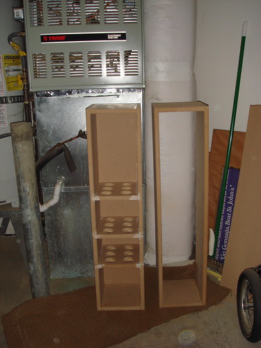
Please critique and comment on them. I pleased with how they came out.
A few tips for those who are first timers like myself.
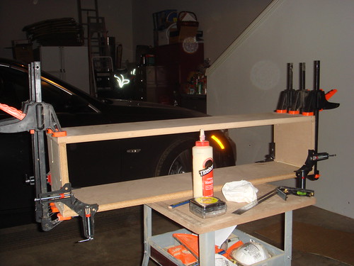
Plan your cuts. This is most important to making something that is square and will glue up well.
Buy some corner clamps. This will make assembly much easier.
Make one end of the corners and all sides of the back and baffle slightly larger than you need. After it's glued up you can come back with a flush trim bit and knock down the excess and you'll have a nice clean edge.
Maybe I should start a build thread?
Please critique and comment on them. I pleased with how they came out.
A few tips for those who are first timers like myself.
Plan your cuts. This is most important to making something that is square and will glue up well.
Buy some corner clamps. This will make assembly much easier.
Make one end of the corners and all sides of the back and baffle slightly larger than you need. After it's glued up you can come back with a flush trim bit and knock down the excess and you'll have a nice clean edge.
Maybe I should start a build thread?
Brewboy said:Since you are from the rose city a little trip down to Woodcrafters will fill the order for "something pretty"
http://woodcrafters.us/
If you have never been there before, be prepared for a life changing experience.
Brewboy-
I've been there and it is amazing and a little intimidating. Looking at your screen name have you ever been to http://www.fhsteinbart.com/
Also do you know of anywhere in Portland where I can get a lesson in veneering?
Thanks.
sploo said:
Always a good idea. I even do it with CNC cut panels I produce, as they never glue together absolutely perfectly (i.e. sub-millimeter). However, IRC, the OP's aim was to produce a sloping box, which would be a bit harder to trim (at least for some of the joins).
While the front, back, top, and bottom are all joined at angles the sides are at 90 degrees and would trim beautifully with a router if they were the pieces cut over sized instead of the traditional baffle + back. Making the front and back over-sized as usual would make getting the top+bottom and sides to match first which would be time consuming and then using a vertical trim sub-base on the router.
I guess you could veneer the top and bottom, trim those with your veneer saw at an angle, and then wrap around the other four sides with up to an inch? to trim off on the corners with the obtuse angle but I'm not a veneer-the-whole-enclosure sort of guy.
djn04 said:Please critique and comment on them. I pleased with how they came out.
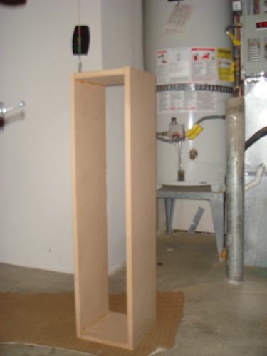
Looking very good indeed. I'd probably have glued the four walls together with them on the rear panel, rather than trying to get them square then putting the panel on, but that's because I'd use a rebated edge around the rear panel.
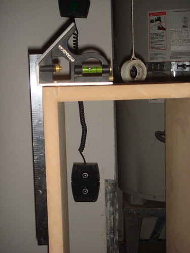
It looks like you've got the walls square, and any imperfections will obviously trim off, as long as you've got the rear panel a little larger than the edges of the four walls. Good progress, keep the pics coming.
BTW While I remember, if you decide to paint them, then make sure you store the finished boxes in the room you want to use them in for a few weeks before you paint - this is so that the moisture level in the MDF is pretty good for the room, and should minimise movement of the panels after painting (this is a big problem with MDF).
For your next project, you should think about making rebates and dados on the panels, as that increases the strength even further, and gets the panels to line up really well. You can see an example of this in a sub I built recently (http://www.diyaudio.com/forums/showthread.php?postid=1685075#post1685075).
The top and bottom panels were slightly oversize, and were trimmed off after gluing. Most of the wall and brace parts also had rebates and dados, to make the joins nice and strong.
This sort of thing is obviously much easier with a CNC machine, but a decent router and a large rebate bit will easily run channels around the edges of a panel, and a 3/4" straight bit, along with a straight edge to guide your router, will make dados through the middle of a panel. Basically, with enough rebates and dados, you'll often find the box will hold together without any glue (just for checking of course, then you drown it in PVA!).
Drew Eckhardt said:I guess you could veneer the top and bottom, trim those with your veneer saw at an angle, and then wrap around the other four sides with up to an inch? to trim off on the corners with the obtuse angle but I'm not a veneer-the-whole-enclosure sort of guy.
I did a pair of veneered speakers for a guy a couple of years ago - it's not something I'd want to repeat in a hurry. I used real wood veneer, not paper backed stuff, and d*mn that was a long job. Bits tearing off when you cut it, having to apply loads of pressure just to glue one sheet etc. etc. I understand why the pros have vacuum bags. Oh, and a lot more patience, and talent, than me.
This was the end result:
http://spikyfish.com/longball/IMG_2213.jpg
http://spikyfish.com/longball/IMG_2218.jpg
sploo said:
For your next project, you should think about making rebates and dados on the panels, as that increases the strength even further, and gets the panels to line up really well. You can see an example of this in a sub I built recently (http://www.diyaudio.com/forums/showthread.php?postid=1685075#post1685075).
That is one finely made sub cabinet. I don't think I have the skills at this point to make the rebates and dados like that. Not to mention the router bits.
I'll post more picks as I progress. I might cheat and have them professionally veneered if I don't think I can produce good results.
djn04 said:That is one finely made sub cabinet. I don't think I have the skills at this point to make the rebates and dados like that. Not to mention the router bits.
Thanks - though you might surprise yourself if you tried. You could do almost all of that with a 1/4" bit + circle cutting jig (for the speaker holes) and a 3/4" bit and a straight length of wood to clamp onto the sheet (so you can route the channels on the sheet).
It would take quite a long time by hand, but with patience I bet you'd find you could do something very similar.
The sheets were made a little larger than required, as they were trimmed off, using the walls as a guide once it was glued together. This is actually quite useful, as it means you can cut these kind of panels by hand (i.e. jigsaw, tablesaw, bandsaw) and, as long as they're a little oversize, you'll get a result as good as CNC, as you trim it all smooth in the end.
EDIT: Nearly forgot - veneering. I understand the paper backed veneers are much easier to use. I'm sure there will be plenty of people here with experience of them (I wouldn't mind knowing myself TBH). You could try picking up a small amount of one you liked, and have a go at veneering a small sheet of MDF (all faces) as a test.
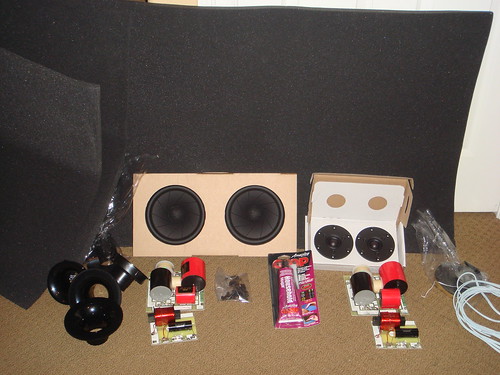
So the kit arrived yesterday and I'm almost finished with the baffles. I have a dumb questions though. The high pass and low pass crossovers came on separate boards my question is how do I wire both of them to the binding posts? do I run separate wires to both of them. Also what is the best method of attaching the wires? Solder? Crimp connectors?
Thanks
Thanks
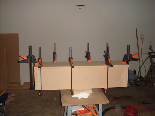
Lookin good! Before you install the baffles I suggest you put more holes in your bracing, they should be 50% holes to be sure they don't restrict airflow.
Soldered connections are always best but you can use crimp connecters by removing the plastic before you crimp and solder the wires in after crimping.
For a very good way to apply veneer try GOOGLing [heatlock].
It is a heat activated adhesive that was designed for paper backed veneer and all you need is a household hand iron to install your veneer. If you follow the directions to the letter I guarantee you will be pleased with the results. I have gone through almost two gallons so far and wont use anything else since I discovered it. They also sell veneer at very competitive prices for one stop shopping.
I dont know if anyone else makes their front baffles the way I do, I apply the veneer before I cut the holes and then cut the holes in the veneer with an arts and crafts circle cutter. I just set it up so the hole in the veneer is a few thousands bigger than the diameter of the cut that the router will make. This eliminates any chance of tearing or splintering the veneer when I rout the holes. The finished product comes out with perfect edges.
Patience and common sense are the most important ingredients no matter what method you use.
Have fun, Bill
Bill
Thanks for the suggestions. I was wondering about the bracing. I'm still confused about the crossover wiring though
I think I'll go with solder with the exception of the driver terminals so I can easily remove them. Now to figure out how to wire them to the binding posts
Thanks for the suggestions. I was wondering about the bracing. I'm still confused about the crossover wiring though
I think I'll go with solder with the exception of the driver terminals so I can easily remove them. Now to figure out how to wire them to the binding posts
The inputs to the x-overs are just paralleled and connected to the binding posts. After you do this you can check your work with an ohmmeter on the binding posts without the drivers hooked up. It should read infinity, if it does not your x-over is miswired because there should not be a DC path through them.
Bill
Bill
djn04 said:So the kit arrived yesterday and I'm almost finished with the baffles. I have a dumb questions though. The high pass and low pass crossovers came on separate boards my question is how do I wire both of them to the binding posts? do I run separate wires to both of them. Also what is the best method of attaching the wires? Solder? Crimp connectors?
Thanks
Without seeing a schematic I wouldn't want to state anything with absolute authority. However, a pair of DIY kit speakers I've got also had split crossovers. The binding posts were for bi-wiring/bi-amping (i.e. there are two positive and two negative posts).
One pair of pos/neg is obviously connected to the low pass crossover, with the other pair to the high pass.
However, if I want to use the speakers without bi-wire/bi-amp then there are joining plates that connect the two positive posts together, and the two negative posts together. I.e. you could just join the two positives to go to one post, and the two negatives to another post.
I suspect I've just given a long winded answer to what Bill Fuss has already said - but hopefully it's useful.
As Bill's already stated - soldered connections are preferred. But, as long as crimped connections are snug (and you're not moving the speakers around on a daily basis) there's no reason not to use them. I've got (what was intended to be a short term) sub prototype, which I bodged together using spade connectors, and it's worked happily for over a year.
I looked at your kits, the tweeter X-over gets wired to the top posts and the midbass goes to the bottom posts. Included are straps to link the two sets of binding posts together. If you would like to try biamping just remove the straps and use separate power amps for the tweeters and midbasses, but you will need some way to set the balance unless the amps are identical in gain. I hope I was clear enough.
Bill
Bill
I'm not using the binding post plate from the kit I ordered a 2 post plate from parts express. If I understand everything correctly I can just solder both positive wires to the positive post and both negative wires to the negative post right?
Thanks to everyone for all your help.
Thanks to everyone for all your help.
djn04 said:If I understand everything correctly I can just solder both positive wires to the positive post and both negative wires to the negative post right?
Yes that sounds right - and what Bill's described is exactly how my kit worked. You do realise that you're not losing anything by having the 4 post terminal plate though? And, as Bill's also indicated, if you remove the straps between the pos/pos and neg/neg on the four post plate then you get the possibility of bi-amping.
Sploo thanks. The picture of the kit on Madisound is a little misleading. The kit is only the drivers and crossovers. You can purchase the rest separately. I got some stuff from them and the rest from Parts Express because it was cheaper. I'm not using the 4 post terminal shown with the kit. I got a 2 post binding plate and posts from Pat Express.
Here's few a pics of the progress

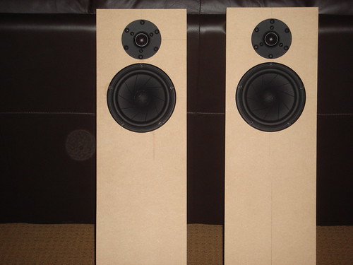
and one of somebody who's starting to sweat
Here's few a pics of the progress
and one of somebody who's starting to sweat
Bill Fuss said:One of your tweeters is upside down.
Yeah I messed that up does it matter other than aesthetics?
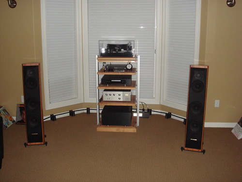
So when I was putting in the bracing I didn't account for the interior flange of the port and now it won't fit because the brace is in the way. Can I leave the interior flange out or hack the top 1/2 inch of the flange off without affecting its performance?
http://www.zaphaudio.com/ZRT-2way-vented.pdf
By the way I wired up one one of them and gave it test and much to my surprise sound came out of it!!!!!!
http://www.zaphaudio.com/ZRT-2way-vented.pdf
By the way I wired up one one of them and gave it test and much to my surprise sound came out of it!!!!!!
- Status
- This old topic is closed. If you want to reopen this topic, contact a moderator using the "Report Post" button.
- Home
- Loudspeakers
- Multi-Way
- Newbie looking for advice and encouragement