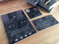
Boards arrived from pcbway.com today, they look good quality to me. I've put together a power supply board and one amp. I realised pretty quickly i should have gone for bigger solder pads as it was difficult to get good contact between the iron tip and the pad. Also I could have allowed a bit more tolerance for the hole sizes, everything fitted but I had to take sandpaper to the legs of the 1W resistor to get them in. I've not left much room to heatsink the diodes if I need to so I might need to think about that.
Hopefully I'll get some time to put together a bulb tester tomorrow so I might get one channel working.
I had one question that I never really understood the answer to - the HBR, I am running two amps from one PS so should I start with a 10ohm resistor or just use a thin copper wire? My only worry is that once I've soldered into those holes it's going to be difficult to clear them again. I was thinking of soldering a couple of headers in there if I can make them fit. Any advice?
Thanks,
Simon.
Attachments
Fit copper wire links. You need two: HBRL & HBRR
If you need to change you can cut the links and bend the two ends up to form headers.
Build one on the bench without any chassis/enclosure.
test that assembly fully and remove all the bugs.
Then fold that strung out assembly into the shape it will be when fitted inside the enclosure. Test again - has the performance changed? debug if necessary.
Repeat for the other channel.
Then fit one into the enclosure and check performance AGAIN. Debug before fitting the second (tested and working) channel.
Test AGAIN.
Last edited:
That's OK - just buy an SMPS later.I've not left much room to heatsink the diodes if I need to so I might need to think about that.
")
That's OK - just buy an SMPS later.
I think you might be right... I already had the toroid, so it was a shame not to use it.Boards arrived from pcbway.com today, they look good quality to me. I've put together a power supply board and one amp. I realised pretty quickly i should have gone for bigger solder pads as it was difficult to get good contact between the iron tip and the pad. Also I could have allowed a bit more tolerance for the hole sizes, everything fitted but I had to take sandpaper to the legs of the 1W resistor to get them in. I've not left much room to heatsink the diodes if I need to so I might need to think about that.
Hopefully I'll get some time to put together a bulb tester tomorrow so I might get one channel working.
I had one question that I never really understood the answer to - the HBR, I am running two amps from one PS so should I start with a 10ohm resistor or just use a thin copper wire? My only worry is that once I've soldered into those holes it's going to be difficult to clear them again. I was thinking of soldering a couple of headers in there if I can make them fit. Any advice?
Thanks,
Simon.
Nice looking boards!
Woo Hoo!
Used the bulb tester with iPhone as input and an old Bose set of speakers - sounded okay, bit of distortion & strange artefacts. I think that was all down to the phone and the cable.
I tried to get close to the final layout of boards (as per AndrewT's suggestion) and plucked up the courage to plug into my main system - computer / record deck -> miniDSP2x4 HD -> Seas A26. Great sound only the tiniest trace of a hiss when putting my ear right up against the tweeters. Subjectively at least as good as my Hypex UCD180s, I'll need to do some more listening.
Sound wise I think it's there however there are some improvements I could make to the boards - mainly the size of the solder pads, it was very fiddly and frustrating trying to get heat into them. I have no idea how anyone manages to neatly solder an inductor, mine was 12 loops of 16 SWG enamel copper and I couldn't get enough heat in there with my biggest solder tip at 400°C.
Anyway, very happy with progress so far - just need to get on with the chassis now.
Thanks again for everyones help.
Heat the PCB pad and the thick copper lead with a big blob of melted solder. Eventually the whole lot heats up and the flux allows the solder to flow. Flood the melted pool with more solder until the joint has a neat meniscus all around the copper.
Then allow to cool without disturbing the very hot joint.
I use 1.6mm to 2mm diameter inductor wire into solid planes and the method works for me, but I use 63/37 which melts freezes at 183degrees C.
Then allow to cool without disturbing the very hot joint.
I use 1.6mm to 2mm diameter inductor wire into solid planes and the method works for me, but I use 63/37 which melts freezes at 183degrees C.
You should not be able to hear any noise, neither hum nor white with an ear close to normal speakers with normal amplifier gains.
eg 88dB/W@1m & 28times gain.
You may be able to measure Hum + Noise with a DMM set to 199.9mVac.
0.0mVac is achievable, 0.1mVac to 0.3mVac is good.
>0.3mVac is poor. >1.0mVac is bad.
0.0mVac on a digital readout means <0.05mVac, not zero noise.
Did you measure your amplifier before you cased it up?
What readings did you get for output offset and output H+N?
Did the readings change after inserting into a metal chassis?
You should not be able to hear any noise, neither hum nor white with an ear close to normal speakers with normal amplifier gains.
eg 88dB/W@1m & 28times gain.
You may be able to measure Hum + Noise with a DMM set to 199.9mVac.
0.0mVac is achievable, 0.1mVac to 0.3mVac is good.
>0.3mVac is poor. >1.0mVac is bad.
0.0mVac on a digital readout means <0.05mVac, not zero noise.
Did you measure your amplifier before you cased it up?
What readings did you get for output offset and output H+N?
Did the readings change after inserting into a metal chassis?
I've not done any measurement of the amp yet, just tested it with the dim bulb tester and a duff set of speakers before plugging it into my good ones. I'm yet to make the chassis so the units haven't made it into a box yet.
I'm interested in measurement and meant to read up on it, but I've spent my time so far learning the design and building the boards. Would I test with a DMM across the speaker terminals with the amp on but no signal in?
Sounds like you've made an excellent job, well done. You can measure the DC offset like that, which is a good idea
Thanks that's nice to hear. I'm going to have a bit of a read up on measurement starting with DC offset. I have a DMM and can lay my hands on a scope but that's a whole new learning experience for me so may take a bit of time. I'm planning on getting the panels for the case CNC'd so I've got a bit of time to read up before I'm 'finished'.
Also I could have allowed a bit more tolerance for the hole sizes, everything fitted but I had to take sandpaper to the legs of the 1W resistor to get them in.
You need more wiggle room that a slip fit as you need the solder to wick into the hole too. What you have will probably work for a bit. Just beware that the solder joint probably isn't as strong as it could have been with the proper hole size.
I've not left much room to heatsink the diodes if I need to so I might need to think about that.
I doubt you need much heat sinking. If you do, there are some clip options that are pretty small. A piece of aluminum with a PEM nut (self-clinching nut) pressed into it would probably work too. Alternatively, a chassis mounted diode bridge could be fitted. All is not lost.
Tom
What you have will probably work for a bit.
Sounds a bit pessimistic... although I might make some changes and get another set of boards made up. Think I'll wait until I feel like I really understand what needs changing.
Thanks that's nice to hear. I'm going to have a bit of a read up on measurement starting with DC offset. I have a DMM and can lay my hands on a scope but that's a whole new learning experience for me so may take a bit of time.
A scope isn't mission critical for bringing the amp up. If you have one, I'd certainly encourage you to learn how to use it and use it to test the amp, but a DMM will get you quite far.
First measure the output DC offset. It should be ±10 mV or less. You can double-check with the LM3886 data sheet, but I seem to recall the typical number is ±2 mV.
Use WavTones to generate a test tone at 400 Hz, 0 dBFS, 5 seconds. Play it on repeat using your media player. Adjust the volume such that you have 100 mV RMS going into the amp. Measure the output of the amp. With the default data sheet values (Test Circuit #2 in the LM3886 data sheet), you should get 2 V on the output. Preferably this test should be conducted with a resistive load (8 Ω), but you can measure without a load.
If you have an actual signal generator that can generate a clean square wave, measuring the transient response of the amp can reveal things such as instability. I generally measure the step response at various capacitive loads and look to see how much capacitance it takes to cause the amplifier to oscillate. So 8 Ω in parallel with 10 nF - 10 uF in logarithmic steps. This does require that you have a clean square wave going into the amp, which many sound cards cannot generate.
Without a proper signal generator, you can still look at the clipping behaviour, though. With a resistive load and that 400 Hz test tone you made earlier playing on repeat, crank the volume knob until the amp clips. Go slowly as the amp behaves differently at the onset of clipping than it does at hard clipping. If the amp is able to enter and exit clipping cleanly, it's probably good to go.
Tom
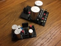
I've tested DC offset with my cheapo DMM and I'm getting a reading of 0.0mV so I thought I'd check that I'm doing this right. I have the amp powered with no load connected and (out of the picture) I'm shorting the input terminals.
When I first switch on I get a reading of <10mV which reduces to 0 over a few seconds. Then when I short the input I get a reading of 1 or 2 mV which quickly goes down to 0. My meter seems to take a few seconds to get an accurate reading e.g. when I measure resistance I need to let the it settle for 5 or so seconds.
Does this sound correct or should I buy another DMM to check this with?
Thanks,
Simon.
Attachments
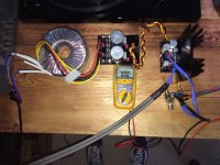
Test #2 - I used REW to create a 400Hz sine wave and using the digital volume control on the miniDSP the closest I could get to 100mV was 102, this gave me 2.08V on the output with a 10W 8R2 as a load. So I guess that sounds about right.
Test #3 - Question - how do measure whether the amp is clipping? Also I don't have a scope at the moment although I do have some software tools capable of creating square waves (REW, Reason etc.) I have no way of checking how they are reproduced at the analogue input.
Thanks,
Simon.
Test #3 - Question - how do measure whether the amp is clipping? Also I don't have a scope at the moment although I do have some software tools capable of creating square waves (REW, Reason etc.) I have no way of checking how they are reproduced at the analogue input.
Thanks,
Simon.
Last edited:
I've just re-done my calcs, I work out max power dissipation as 35.9W and I've got the insulated version of the IC so I need <1.3C/W... so looks like you're right - I need to find a bigger heatsink. I think I can get a taller one... does the premise of the idea cause any problems?
Did you included the musics crest-factor? Modelling a system for worst-case continuous sinewave-output is nice for measurements but not related to real world usage.
Did you included the musics crest-factor? Modelling a system for worst-case continuous sinewave-output is nice for measurements but not related to real world usage.
No but you've just given me a new search term for Google
Thanks.- Status
- This old topic is closed. If you want to reopen this topic, contact a moderator using the "Report Post" button.
- Home
- Amplifiers
- Chip Amps
- Newbie LM3886 Circuit