Hi, jean-paul. thank for your suggestions.
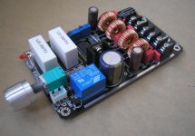
This is a DC supply board and i have to prevent polarity reverse, that's why i don't put elec-caps before the relay. May be it's better to add a PSU board for best use.
About CN2 and K3, they seem very logical for layout now and i will show the layout behind. so it's ok i think.
For LEDs, i place a protection LED near the right uper coner to prevent long distance route. I think it's better to use wire to mount it on the front panel if necessary.
And for J1, same reason for place it near the pot, the track will be shortest. it's also keep same as V2.0 does.
I have to explain how V1.1B comes.For this version, it's not paralleled, so it will be V1.x, and i already have V1.0 before. V2.x means paralleled power stage boards(there is just V2.0 now).
I will consider all of your advice and do changes when it's needed, and I also may take some of them for my other products.
Hi, I am happy that you accept comments on your designs. If you like i can advise you since I had my last working day for this company yesterday. I have joined the army of the unemployed after years of hard work and having no time for myself. So I have some spare time for now. I will need to find a job ASAP though.
I don't get the remark that you have to protect for reverse polarity !? You could use a sturdy diode in anti-parallel to prevent for the dumbest of all possible user errors
Please consider the fact that everything that's added in the power line is a failure possibility and it will have an influence on the resistance/impedance of the power lines too. I could understand if you would incorporate a AC 90- 250V SMPS on the PCB. Everything in one hand by the same designer. I opened quite a few SMPS adapters that power my class t amps and they have the worse of component choices. What is the use of good parts on the amp PCB then ? Besides that they often fail prematurely as they have a totally closed case that offers no convection/airflow. They are always on and draw some power and when they fail they do so when you are not at home. I don't like the thought of that. The switches that switch the amps on don't like to switch large DC inrush currents as they have soft gold clad contacts that will burn in because of DC. I like to switch AC power as it does not stress parts as much and it is more "green" ( and safe ) as the device won't draw power when it is off. Better is an open chassis SMPS and the best solution is to make it all on one PCB of course with all the safety guide lines and enough space between AC 90 - 250V carrying parts and the amp area. Please check the B&O IcePower modules, they are a good example of that. They are opposite the much more common approach of modular design. I don't know who invented it but the flexibility that is offered is seldom used in practice and one tends to forget the harness/time loss costs that come with modular design. Let's not discuss the sonical character of the IcePower modules though.
I hope you the advantages now of a simple reliable power transformer with a plain jane power switch
Don't worry about the reverse polarity too much. If the PCB has the right marking it is clear how to connect it. The extra relay will only add to the costs, the PCB mounted switch would also make it more difficult for the unexperienced to drill a hole on the right spot in a case etc. Or will you be offering this amp in a case or even under a certain brand name ? Larger tank caps will make the amp sound better and a more worthwhile investment. Since you used output relays there won't be any plop while power on so please explain the power relay. I still advise on larger caps than 1800 uF, you were on the right track with the current version 2.0.
Last edited:
Not parallel?
Why bother with the not paralleled power stage at this point when you have the V2 done? Smaller size? Saves one chip? The single chip version can not drive 4 ohm speakers correct?it's not paralleled, so it will be V1.x, and i already have V1.0 before. V2.x means paralleled power stage boards(there is just V2.0 now).
Hi, I am happy that you accept comments on your designs. If you like i can advise you since I had my last working day for this company yesterday. I have joined the army of the unemployed after years of hard work and having no time for myself. So I have some spare time for now. I will need to find a job ASAP though.
I don't get the remark that you have to protect for reverse polarity !? You could use a sturdy diode in anti-parallel to prevent for the dumbest of all possible user errors
Better is an open chassis SMPS and the best solution is to make it all on one PCB of course with all the safety guide lines and enough space between AC 90 - 250V carrying parts and the amp area. Please check the B&O IcePower modules, they are a good example of that. They are opposite the much more common approach of modular design. I don't know who invented it but the flexibility that is offered is seldom used in practice and one tends to forget the harness/time loss costs that come with modular design. Let's not discuss the sonical character of the IcePower modules though.
I hope you the advantages now of a simple reliable power transformer with a plain jane power switch
Don't worry about the reverse polarity too much. If the PCB has the right marking it is clear how to connect it. The extra relay will only add to the costs, the PCB mounted switch would also make it more difficult for the unexperienced to drill a hole on the right spot in a case etc. Or will you be offering this amp in a case or even under a certain brand name ? Larger tank caps will make the amp sound better and a more worthwhile investment. Since you used output relays there won't be any plop while power on so please explain the power relay. I still advise on larger caps than 1800 uF, you were on the right track with the current version 2.0.
Hi, intersting information
, i will do more work later.And about power relay, it's just in case of polarity reverse. That will be a big trouble when a mistake really happen, may be most of the chips on board will burn then. About the caps, i prepare a PSU too, then the total caps will be big enough
Why bother with the not paralleled power stage at this point when you have the V2 done? Smaller size? Saves one chip? The single chip version can not drive 4 ohm speakers correct?
Hi Sendler.
V2 is for 4ohm high power(100W) and V1 is for 6/8ohm lower power(50W). so both will meet their own demand i think. no?
cheaper?
There will be a demand for the single chip amp only if it happens to sound better for some reason. I would have to assume that the difference in price will be negligible so why not buy the more powerful amp for a few dollars more.
Hi Sendler.
V2 is for 4ohm high power(100W) and V1 is for 6/8ohm lower power(50W). so both will meet their own demand i think. no?
There will be a demand for the single chip amp only if it happens to sound better for some reason. I would have to assume that the difference in price will be negligible so why not buy the more powerful amp for a few dollars more.
Sendler has a point: it will only sell if it sounds better otherwise there won't be a need for a low power version. There are plenty TA2020/21 designs around. If you use a somewhat lower voltage on the V2.0 it will be a low power version too
Optimising/enhancing the V2.0 with the above mentioned features would be a wiser choice.
Optimising/enhancing the V2.0 with the above mentioned features would be a wiser choice.
Last edited:
Sendler has a point: it will only sell if it sounds better otherwise there won't be a need for a low power version. There are plenty TA2020/21 designs around. If you use a somewhat lower voltage on the V2.0 it will be a low power version too
Optimising/enhancing the V2.0 with the above mentioned features would be a wiser choice.
, I think there is difference sound between them, but very subjective. and if use higher power chip on V1, it will also ok for 4ohm and not bad i think.The single chip version can not drive 4 ohm speakers correct?
It can with a beefier power stage chip, like STA517B or STA516, or some Apogee chips. A lot of them can deliver far more than the 3A rated Tripath power stage....

There will be a demand for the single chip amp only if it happens to sound better for some reason. I would have to assume that the difference in price will be negligible so why not buy the more powerful amp for a few dollars more.
I myself would be interested in trying the singlechip 2*50W version.
I think earlier in this thread, or was it in the sure thread, that someone says that the 41hz amp4 (dual-chip) vs the amp11 (single-chip) is similar but has some differences in sound. That the amp4 has a even nicer midrange, but amp11 has better bass. It kind of reminds me of the terms used to describe single ended vs push-pull tube amplifiers.
If bi-ampling it could make sense to use the paralleled for bass and the singlechip for mid/highs..
Any other input about the potentional interest in the 50W version? I'm sure hifimidiy wouldn't want to make this just for me.
ok, maybe I'm mixing the numbers of the 41hz amps..Amp 4 might have 2 chips, but drives 2 channels
Amp 11 has 1 chip and drives 1 channel
So it remains at 1 chip per channel...
or I misunderstood.
But anyway I think there will be a difference in sound that I would like to check out.
Amp 4 might have 2 chips, but drives 2 channels
Amp 11 has 1 chip and drives 1 channel
So it remains at 1 chip per channel...
Nope, AMP4 is one TK2050 chipset driven in stereo, so two full bridges.
AMP11 is one TK2050 chipset driven in mono bridged parallel mode, so two full bridges paralleled.
AMP11 has twice the damping factor which can make it a tad unforgiving in the higher range. This makes AMP4 a tad more fluent. Both feature excellent bass, but AMP11 could provide more control over larger (sub)woofers.
Generally these amps are a lot better at both component choice, design quality and sound quality than any other TK2050 product I've come across so far. I would be quite surprised if someone can beat that, disregarding the price. There's more to a good design than placing parts on a platter and connecting the dots...
Hi,
Since I'm very interested on these boards for a multichannel amp. - I'll add my (newbie) insights and requests :
I'd like to have a flexible solution with the ability to easily drive both 4ohm and 8ohm w/o the need for modification or replacing the whole board when experimenting with different speakers...
-Good for us to have you on BOARD jean-paul Seems like you know what you are saying and I'm sure we'll all benefit from the improvements you suggested
(great learning opprtunity for a newbie like me)
-I myself would certainly be interested on an SMPS designed for these boards with good components and same great quality - but would still prefer to get it on a separated module to allow more flexibility and perhaps better efficiency (multiple boards, separated compartment etc.) - I feel that boards with builtin SMPS are interesting but a bit limited for future enhancements and usually less cost efficient (unless you'll surprise me )
Alternatively, since decent and cheap SMPS (like the Meanwell) are common- you could offer an optional power "enhancer" add-on - like the popular John Linsley Hood Ripple Eater which I personally would add to all my next builds since it's so cheap and seem to perform so well even with cheaper PSUs...
-I wouldn't degrade any performance or add unnecessary components just to prevent reverse polarity or wiring errors - If the markings are good and so is the support from this forum - there is no reason to get it wrong (I probably will - but thats another story). If someone really insist making such errors - there are so many options to burn the board that I just wouldn't bother making it "fool proof"...
Additional personal requests:
-I'd like to get the board with the most recommended upgrade components from this forum or other discussion regarding the TK2050 boards - like the Wurth XXL inductors that seems to perform better and shouldn't cost much more or complicating the build.
For some of us who don't have spare components laying around, It's much harder to source these on our own and I'd defiantly prefer get an already optimized board - or at least an optional "upgrade" pack with optional components I can experiment with (don't mind soldering etc. - it's sourcing the parts that is a problem for some of the newbies )
- I'd also like to have the volume potentiometer placed in a different location - preferably on the shorter side of the board - or at least offer it as an option/ modular component. In it's current location it's really hard to build a multiple board setup (like I plan to do) where two or more boards can be placed next to each other...
- Same with the additional power switch you intend to implement - I'll controlling the PSU directly and won't care for additional switch on the board - unnecessary added space and cost IMHO
That's all (for now) - I can't wait to see how the new and improved versions will come out (soon I hope )
Regards,
Gal
Since I'm very interested on these boards for a multichannel amp. - I'll add my (newbie) insights and requests :
Boards that are limited to either 6/8ohm or 4ohm are much less attractive (to me at least).Hi Sendler.
V2 is for 4ohm high power(100W) and V1 is for 6/8ohm lower power(50W). so both will meet their own demand i think. no?
I'd like to have a flexible solution with the ability to easily drive both 4ohm and 8ohm w/o the need for modification or replacing the whole board when experimenting with different speakers...
I'd partially agree with that as well - I wouldn't mind sacrificing watts for significantly better sounding board (or much smaller/cheaper) - but if the differences are negligible, than more total power is better - perhaps since we can get the same output level with less THD - correct !?There will be a demand for the single chip amp only if it happens to sound better for some reason. I would have to assume that the difference in price will be negligible so why not buy the more powerful amp for a few dollars more.
Hi, I am happy that you accept comments on your designs. If you like i can advise you since I had my last working day for this company yesterday. I have joined the army of the unemployed after years of hard work and having no time for myself. So I have some spare time for now. I will need to find a job ASAP though.
I don't get the remark that you have to protect for reverse polarity !? You could use a sturdy diode in anti-parallel to prevent for the dumbest of all possible user errors
Better is an open chassis SMPS and the best solution is to make it all on one PCB of course with all the safety guide lines and enough space between AC 90 - 250V carrying parts and the amp area. Please check the B&O IcePower modules, they are a good example of that. They are opposite the much more common approach of modular design. I don't know who invented it but the flexibility that is offered is seldom used in practice and one tends to forget the harness/time loss costs that come with modular design. Let's not discuss the sonical character of the IcePower modules though.
I hope you the advantages now of a simple reliable power transformer with a plain jane power switch
Don't worry about the reverse polarity too much. If the PCB has the right marking it is clear how to connect it. The extra relay will only add to the costs, the PCB mounted switch would also make it more difficult for the unexperienced to drill a hole on the right spot in a case etc. Or will you be offering this amp in a case or even under a certain brand name ? Larger tank caps will make the amp sound better and a more worthwhile investment. Since you used output relays there won't be any plop while power on so please explain the power relay. I still advise on larger caps than 1800 uF, you were on the right track with the current version 2.0.
-Good for us to have you on BOARD jean-paul
Seems like you know what you are saying and I'm sure we'll all benefit from the improvements you suggested (great learning opprtunity for a newbie like me
)-I myself would certainly be interested on an SMPS designed for these boards with good components and same great quality - but would still prefer to get it on a separated module to allow more flexibility and perhaps better efficiency (multiple boards, separated compartment etc.) - I feel that boards with builtin SMPS are interesting but a bit limited for future enhancements and usually less cost efficient (unless you'll surprise me
)Alternatively, since decent and cheap SMPS (like the Meanwell) are common- you could offer an optional power "enhancer" add-on - like the popular John Linsley Hood Ripple Eater which I personally would add to all my next builds since it's so cheap and seem to perform so well even with cheaper PSUs...
-I wouldn't degrade any performance or add unnecessary components just to prevent reverse polarity or wiring errors - If the markings are good and so is the support from this forum - there is no reason to get it wrong (I probably will - but thats another story
). If someone really insist making such errors - there are so many options to burn the board that I just wouldn't bother making it "fool proof"... Additional personal requests:
-I'd like to get the board with the most recommended upgrade components from this forum or other discussion regarding the TK2050 boards - like the Wurth XXL inductors that seems to perform better and shouldn't cost much more or complicating the build.
For some of us who don't have spare components laying around, It's much harder to source these on our own and I'd defiantly prefer get an already optimized board - or at least an optional "upgrade" pack with optional components I can experiment with (don't mind soldering etc. - it's sourcing the parts that is a problem for some of the newbies
)- I'd also like to have the volume potentiometer placed in a different location - preferably on the shorter side of the board - or at least offer it as an option/ modular component. In it's current location it's really hard to build a multiple board setup (like I plan to do) where two or more boards can be placed next to each other...
- Same with the additional power switch you intend to implement - I'll controlling the PSU directly and won't care for additional switch on the board - unnecessary added space and cost IMHO
That's all (for now) - I can't wait to see how the new and improved versions will come out (soon I hope
)Regards,
Gal
like the Wurth XXL inductors that seems to perform better and shouldn't cost much more or complicating the build.
The toroidal coils that are used on this board are always better than the Wurth coils. The toroidal coils are faaaaaar better in getting rid of heat, have smallest possible stray field by nature, only take more work to wind.
I wouldn't want that changed in the design!
Only when wound by hand the quality can be poor because they are easily wound too loose. Loose windings at 200mhz+ freq. can generate a lot more heat, this I have recently measured in practise.....
Thank you for the comment - I have to admit I haven't heard either of these - just repeating some feedbacks from other users experiences.
Perhaps someone who actually tried these can verify or share his experiences again?
Gal
I've tried a truckload of different chokes myself, Panasonic, Murata, Wurth, aircores, Toroidal...
In case of problems, for instance serious overheating chokes the toroidal chokes always performed best. Audible differences there are, but usually due to non linearities in the resulting frequency response curve, not the actual quality of sound itself. This then comes down to a matter of preference and has nothing to do with performance....
The performance I am speaking of merely comes down to the pure technical performance in terms of EMI and heat.
Sound vs efficiency
The E-Carbonyl toroids have an opaque type of sound. The Wurth or Sagami coils sound much more transparent. Ferroxcube toroids sound good but run hotter and leak RF like an air core. It all depends if you favor theory and temp measurements or sound. I don't use my amps in a portable, battery powered application so I prefer to optimize for sound rather than efficiency.
Thank you for the comment - I have to admit I haven't heard either of these - just repeating some feedbacks from other users experiences.
Perhaps someone who actually tried these can verify or share his experiences again?
Gal
The E-Carbonyl toroids have an opaque type of sound. The Wurth or Sagami coils sound much more transparent. Ferroxcube toroids sound good but run hotter and leak RF like an air core. It all depends if you favor theory and temp measurements or sound. I don't use my amps in a portable, battery powered application so I prefer to optimize for sound rather than efficiency.
- Status
- This old topic is closed. If you want to reopen this topic, contact a moderator using the "Report Post" button.
- Home
- Amplifiers
- Class D
- New TK2050 board