I think there may be some questions I missed, pls post again if you want to ask and I will try to help.
-hifimediy
There was a question about the T3e psu with new 20000uf caps. Do you think this will be a problem if used with Meanwell 350 smps?
Hi, for this issue, I agree that remove one of the 10000uF capacitors when work with Meanwell s-350. And later, we will sell 2 kind of T3e for different using: 10000uF*2 for transformer and 4700uF*2 for SMPS.There was a question about the T3e psu with new 20000uf caps. Do you think this will be a problem if used with Meanwell 350 smps?
")
14000
I have 14,000 uf following my MeanWell with no problems.
There was a question about the T3e psu with new 20000uf caps. Do you think this will be a problem if used with Meanwell 350 smps?
I have 14,000 uf following my MeanWell with no problems.
Hi, for this issue, I agree that remove one of the 10000uF capacitors when work with Meanwell s-350. And later, we will sell 2 kind of T3e for different using: 10000uF*2 for transformer and 4700uF*2 for SMPS.
Thanks. Two more questions:
Does the T3 invert phase at the output?
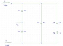
If the big coils are replaced with 4.7uH coils, what caps need to be changed and to what value?
.47uf
I use .47uf with the 4.7uH coils and I also like to add a zobel with .47uf and 14R.Thanks. Two more questions:
Does the T3 invert phase at the output?
If the big coils are replaced with 4.7uH coils, what caps need to be changed and to what value?
I use .47uf with the 4.7uH coils and I also like to add a zobel with .47uf and 14R.
There are 4 capacitors after each pair of inductors. Should all 4 be .47uF?
I installed the Wurth 4.7uH coils in my T1 to good advantage sonically, but left the original cap.s alone.
I don't want to leave the job half done. What (if any) are the pitfalls to running
with the original cap.s?
.22
It looks like the original caps are .22uf in the T1 according to the schematic so you are listening to even less filter than I am. I haven't ever played with an amp using only one output chip for two channels (not paralleled) so I am not sure why they used half value there compared to the other amps. I have also never compared how much audibility between different types of caps of the same value there is in this application. In signal coupling the input there is a big difference with installing the Dayton foils. At speaker level on the output, maybe not so much. You can parallel another .22uf under each of the original caps, C22, 23, and 26 to hear how it will sound but sometimes when bypassing one cap with another at ratios of less than 1:10 you can get a result that starts to sound like you are listening to two different caps. C4 is .1uf? Just leave it unless you want to try an upgrade. If you really want to dial it in you can also try tuning the resistance in the Zobel to something higher than 10R. I tuned this by ear by installing 10 1/4 watt, 100R resistors paralleled together and clipping off one at a time until I just started to hear some glare to determine the best value to replace with a 5 watt resistor. Around 13-14R.
There are 4 capacitors after each pair of inductors. Should all 4 be .47uF?
I installed the Wurth 4.7uH coils in my T1 to good advantage sonically, but left the original cap.s alone.
I don't want to leave the job half done. What (if any) are the pitfalls to running
with the original cap.s?
It looks like the original caps are .22uf in the T1 according to the schematic so you are listening to even less filter than I am. I haven't ever played with an amp using only one output chip for two channels (not paralleled) so I am not sure why they used half value there compared to the other amps. I have also never compared how much audibility between different types of caps of the same value there is in this application. In signal coupling the input there is a big difference with installing the Dayton foils. At speaker level on the output, maybe not so much. You can parallel another .22uf under each of the original caps, C22, 23, and 26 to hear how it will sound but sometimes when bypassing one cap with another at ratios of less than 1:10 you can get a result that starts to sound like you are listening to two different caps. C4 is .1uf? Just leave it unless you want to try an upgrade. If you really want to dial it in you can also try tuning the resistance in the Zobel to something higher than 10R. I tuned this by ear by installing 10 1/4 watt, 100R resistors paralleled together and clipping off one at a time until I just started to hear some glare to determine the best value to replace with a 5 watt resistor. Around 13-14R.
Audio source is as follows:
Laptop -> USB-dac -> miniDSP -> T1&T2
The same exactly setup where amps where tested when I received them... and there were no pop noises then
The only changes is that now is all almost assembled.
Anyway, I'll try with another laptop and see if it gets better.
Tks!
Ok, I did some tests and it's now clear that problem it's in fact not in amps, but in minidsp -the way minidsp switchs off-.
- Tested both amps with line inputs disconnected. No pop on switch-off.
- Tested amps in actual installation, but minidsp powered both by external 5.7v phone adapter (actual) and also by USB cable. NO pop on switch-off if computer is kept on after switching-off amps.
Problem seems to be when minidsp is powered by external ps; it goes off before amps go off. Maybe a relay to delay minidsp switch off will solve this?
If you really want to dial it in you can also try tuning the resistance in the Zobel to something higher than 10R. I tuned this by ear by installing 10 1/4 watt, 100R resistors paralleled together and clipping off one at a time until I just started to hear some glare to determine the best value to replace with a 5 watt resistor. Around 13-14R.
Hi Scott,
What are pros and cons having the Zobel at the output?
Your opinion, please.
Baki
Peak control
A zobel will help control the out of band peak that results from my "improper" 4.7uH/ .47uf filter. Too high a resistance, too little function, slight glare. Too low a resistance, slight loading of the amps and slightly more filtered sound on top.Hi Scott,
What are pros and cons having the Zobel at the output?
Your opinion, please.
Baki
All four
I looked at my circuit again and was reminded that I am using .47uf Dayton foil caps at all four positions in the filter.
There are 4 capacitors after each pair of inductors. Should all 4 be .47uF?
I installed the Wurth 4.7uH coils in my T1 to good advantage sonically, but left the original cap.s alone.
I don't want to leave the job half done. What (if any) are the pitfalls to running
with the original cap.s?
I looked at my circuit again and was reminded that I am using .47uf Dayton foil caps at all four positions in the filter.
Attachments
im needing to power these two boards ... im looking at this but i feel the 25k switching frequency is too low and will cause noise ?!? any views would be good
24V DC 8.3A 200W Regulated Switching Power Supply on eBay (end time 21-Mar-11 11:37:52 GMT)
24V DC 8.3A 200W Regulated Switching Power Supply on eBay (end time 21-Mar-11 11:37:52 GMT)
why not buy the meanwell s-350 ? plenty of positive feedback available.
you don't get the most out of the amp at 24V and according to measures, distorsion is getting better (ie lower) with higher power supply.
Meanwell S-350 are also are fixed switching freq at 25kHz. No noise.
edit : I realize this link is also a meanwell, less powerfull.
you don't get the most out of the amp at 24V and according to measures, distorsion is getting better (ie lower) with higher power supply.
Meanwell S-350 are also are fixed switching freq at 25kHz. No noise.
edit : I realize this link is also a meanwell, less powerfull.
25K
My 25KHz SMPS sound way better than my best liear supply. No problem. The S-350 MeanWells are a steal. They have a newer S-320 version that switches at 90KHz but they are hard to find.
im needing to power these two boards ... im looking at this but i feel the 25k switching frequency is too low and will cause noise ?!? any views would be good
24V DC 8.3A 200W Regulated Switching Power Supply on eBay (end time 21-Mar-11 11:37:52 GMT)
My 25KHz SMPS sound way better than my best liear supply. No problem. The S-350 MeanWells are a steal. They have a newer S-320 version that switches at 90KHz but they are hard to find.
If the higher voltage capacity isn't used, then the sound is essentially the same. If the voltage is raised, you can get stronger peaks plus much less distortion ... These amps sound best at about 60% of maximum power as mandated by rail voltage. Raise the rail voltage and you raise that 60% bar.
Aha, found it! Kristleifur, this 60% figure has been stuck in the back of my mind for a while. And this is the post that put it there.
Can you point me at someplace where I can start to learn more about why 60% is optimum as opposed to some other level, or does it just come out of general how-class-D-works theory? Anyway, interested to know more.
Thanks!

It looks like the original caps are .22uf in the T1 according to the schematic so you are listening to even less filter than I am. I haven't ever played with an amp using only one output chip for two channels (not paralleled) so I am not sure why they used half value there compared to the other amps.
This is done to achieve maximum linearity with the expected load. A non paralleled TP2050 can not drive 4 ohm loads very well, hence the filter is optimised for 8 ohm loads with the .22 caps.
The paralleled version is well capable of driving 4 ohm loads and it is expected to drive such loads (subwoofers, car audio etc...)
If you want more sweetness then I strongly suggest you get a non paralleled TK2050 amp for once and discover the difference!
Your output filter changes are mere EQ-ing of the audio band, an effect not very desired in an amplifier, hence the attempts of the designers to optimise the filter to the load to achieve maximum linearity.
You can just as well buy a nice equalizer to get the same effects...
Last edited:
I tuned this by ear by installing 10 1/4 watt, 100R resistors paralleled together and clipping off one at a time until I just started to hear some glare to determine the best value to replace with a 5 watt resistor. Around 13-14R.
How was this done then? With through hole resistors I suspect? So you had a nice high inductance resistor there and then 'tuned' it to the ear by lowering the 'resistance'?
Ok...so much for science....
The time you spent on all this...

Last edited:
My 25KHz SMPS sound way better than my best liear supply. No problem. The S-350 MeanWells are a steal. They have a newer S-320 version that switches at 90KHz but they are hard to find.
there are a couple of 320's on ebay but they are more expensive ! so i think i'll just go for the 350 as im trying to keep this build a budget one !
im a bit confused though because the advert for the s-350's are rated at 48V !!!! and it says
This is 48V and not suited for tk2050 v1 and v2 amps
oh my mistake i was looking at the wrong one...they do a 27V on too ! lol
Last edited:
- Status
- This old topic is closed. If you want to reopen this topic, contact a moderator using the "Report Post" button.
- Home
- Amplifiers
- Class D
- New TK2050 board