Just a couple of techical questions.
1. Since this board already has a bridge rectifier and if we want to use a different psu - is it possible to solder the rectified voltage Vdc from (for instance) batteries directly to the legs on cap C48? - if so - what is the limit of Vdc here? ( I assume it is approx 31Vdc ?)
If we connect Vdc to the terminals would it not be rectified 2 times? I am not sure how that works..
2. Is the input caps really necessary?. Lets say we have output caps on the dac with value 3.3uf and relative short signal cables.
Is it then possible to solder the input signal directly to R4 and R1? (Assuming to use the board as a power amp) ?
You can connect DC directly to the 4700uf cap. Voltage limits will be 1V less.
I connected my dac directly to the amp without any caps first, and it worked fine, but later I connected two 1uf POI caps. And the sound is still amazing, didnt experiment too much going back and forth with cap/no cap there, it is still so much better with the cap then through the dac's output stage.
If you removed the vol pot on the board, you could maybe do with only one set of caps, but Hifimediy said something about that two voltages could sometimes cancel out each other...
theoretically you can also measure the vibrations in the air which also lead in heat. This is usually notified in dB (you said it yet also). But current measurements are easier to handle than different sonic waves out from the speakers. For example you supply the speaker with 5 W amp power. If your speaker produces 4 W heat that means to me 1 W is converted in sonic or air movement, vibrations - call it as you like. That´s also heat/energy.
So I could also say that an amp produces current and not watt...
Could I go out in the street and measure Watt from surroundings?
I don't quite follow your thoughts about the speakers heat generation. Normally speakers loudness output is measured in dB produced for 1 Watt, for example 90dB/1W. (althought this measurment can be misleading because it is not defined the other surrounding parameters like room size ..)
Every speaker produce heat, some have complicated crossovers which will use lots of the signal before it gets to the speaker, and some speakers don't have a crossover.
i guess you could calculate or measure how many Watts are wasted in the crossover. But in the speaker ? If you had a "perfect" speaker which didn't produce any heat, how many dB would you get from 1W?
What about the uH value on both the boards?
I assume coils are 10uH but I ask you.
And what changes in audio listening using a lower (or higher) uH value?
How to adeguate the output cap values if using other coils (lower or higher uH)?
Thanks!!
We use 11uH on V1 and V2 boards now. Please refer to the attach file to calculate the values. Co=0.47uF on V2, and 0.33uF on V1.
")
Attachments
Schematics in manual are incorrect: C1 and C2 are not onboard. There is room for them, but they are not installed.
Without C1 and 2, you can desolder the pot and directly connect dac out without caps from the dac side, or without caps on the amp side.
you will need to have caps once in the line though..
about the canceling out of the bias: it might be that some dacs have 2.5v bias on the output, but if the tc2000 bias is higher/lower, problems might occur (even from 10mV differences). Would not advise anyone to try that.
With 110mA @ 30V you're at only 3W... raising up the volume the current consumption have necessarily to increase.According to the datasheet the "supply current" (by which I think they mean Idle current) is 60 mA, so the figure sounds about right to me with two channels running.
/U.
Also from idle to the max voulme the current consumption can't be always the same.
My 2 cents...
Schematics in manual are incorrect: C1 and C2 are not onboard. There is room for them, but they are not installed.
Without C1 and 2, you can desolder the pot and directly connect dac out without caps from the dac side, or without caps on the amp side.
you will need to have caps once in the line though..
about the canceling out of the bias: it might be that some dacs have 2.5v bias on the output, but if the tc2000 bias is higher/lower, problems might occur (even from 10mV differences). Would not advise anyone to try that.
These two caps are 100pF normally. As I test, they are used to prevent noise when plug-in(or plug-out) the input cable duiring amp working. But it's ok to unuse them if there is a pot. Unsolder these caps are better for sound quality.
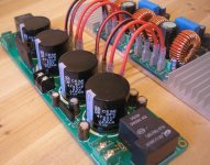
don't know how it sounds, but it looks good the PSU form factor is interesting and will make housing easy.
This has 4x4700µF. Isn't that too less for a linear supply at such power ?
I would go for 4x10 000µF. Should not increase cost much, but will surely provide a better power tank.
the PSU form factor is interesting and will make housing easy.This has 4x4700µF. Isn't that too less for a linear supply at such power ?
I would go for 4x10 000µF. Should not increase cost much, but will surely provide a better power tank.
I have just measured the current on v2 board and read 0.15 (150ma) on idle.
Measured v1 board again with 87dB/1W speakers, turned up a bit, not crazy loud (have quite small room), and read between 1.3 and 1.8, so 130 - 180mA.
Now I suddenly feel so "green"
don't know how it sounds, but it looks good
This has 4x4700µF. Isn't that too less for a linear supply at such power ?
I would go for 4x10 000µF. Should not increase cost much, but will surely provide a better power tank.
Hi, consider that most times we will use a SMPS, 4700uF is not a bad idea. And there is room to fit in bigger caps if needed.
i guess you could calculate or measure how many Watts are wasted in the crossover. But in the speaker ? If you had a "perfect" speaker which didn't produce any heat, how many dB would you get from 1W?
it isn´t correct that just only the crossover produces heat. Why else should all chassis manufacturers spent time and money to optimize the cooling system on the magnets ? In thermodynamics is 1 watt = 1 joule per second. Heat and energy are both measured in joule - better in temperature increase of a isolated system. To get the right joule values you also need the heat capacity of the system. You can also define electric energy like the calculation W = Volt * Ampere. This calculation does also not regard the heat production in the copper cable for example. Total energy split in heat energy (what we don´t wish) and translation/movement energy (that´s preferred). dB measurements are different and complex to convert in watts.
Usually they measure dB of a microfon in 1 meter distance and 1 watt amp power. Maybe you know the standard calculation which says that you have everytime double the power to increase +3 dB.
I am nearly sure that I am writing about things you already know ... so excuse me if I act a bit like an teacher (I am writing much when the day is long
) - but who knows, maybe another reader was cleared up ...Have a nice day
Hope you like it
Hi, if I am right I can connect this PSU with an SMPS ? The board should stand at least 10 amperes current by 36 volts supply I think...
Hi, if I am right I can connect this PSU with an SMPS ? The board should stand at least 10 amperes current by 36 volts supply I think...
yes, the traces on pcb and the connector/wire can stand current of 10A. You may use up to 50V DC to get maxium output power.
now i am confusedHi, consider that most times we will use a SMPS, 4700uF is not a bad idea. And there is room to fit in bigger caps if needed.
This is a linear PS board, with rectifier and filtering+tank caps. Only needs a transformer and done. In this use case, caps need to be bigger.
If SMPS is used, there is no need for an additional PS board, correct ?
The only reason I can see to use this PS board with SMPS, is to benefit from the tank caps. But then, why bother with a board : simply wire one large cap or more in parallel up to the desired tank size.
Sorry, i just don't get the use case you have in mind for this PS board.
Can you share the schematic of the PS board ?
100% correct imho.now i am confused
This is a linear PS board, with rectifier and filtering+tank caps. Only needs a transformer and done. In this use case, caps need to be bigger.
If SMPS is used, there is no need for an additional PS board, correct ?
I agree with you. Notice that with SMPS you don't need large tank caps, instead they could create some problem to the SMPS for some reasons related to its feedback circuit.The only reason I can see to use this PS board with SMPS, is to benefit from the tank caps. But then, why bother with a board : simply wire one large cap or more in parallel up to the desired tank size.
Bye
- Status
- This old topic is closed. If you want to reopen this topic, contact a moderator using the "Report Post" button.
- Home
- Amplifiers
- Class D
- New TK2050 board