Ok, here we go
I guess this is also called Scientific Notation and this is also how they set up Floating Point numbers ...
The "e" in our Akabak script stands for 10 and then the following number is "to the power of"
So 5e3 is the same as: 5 multiplied by 1000 (e=10 to the power of 3)
Scientific Notation
The Floating-Point Guide - Floating Point Numbers
Coordinated or clumsy
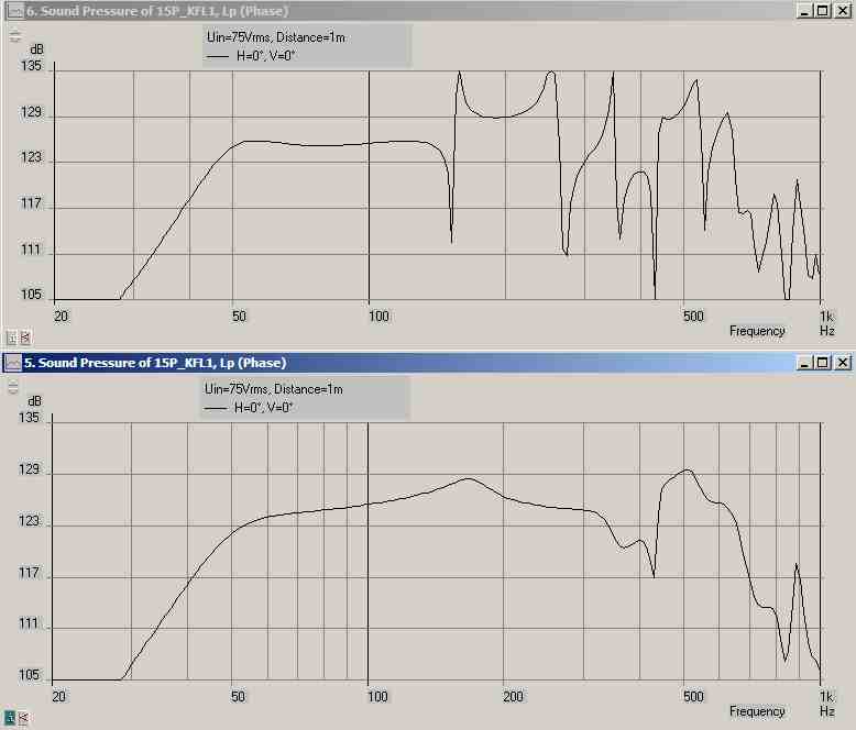
Here is an example of the minor changes (mainly in upper response) you can get when adding vertical (y and y-) coordinates to the radiator parts of a traditional K-aperture in Akabak .... I used 6 radiators in this sim spaced from top to bottom on the front of a cabinet that is 24 inches tall .......
The graphs are for on-axis response, i would imagine that the differences in vertically off-axis response might be more pronounced....
Still need to build out the front chamber properly in this script (i will use TB's example as a guide) and then i will be posting this script along with a rough sketch of this triple chamber Karflex for review ...
Attachments

I did a sensitivity analysis and started with 15 segments for a K aperture and went down. I found that at 9 segments it was about the same as 15 but less than 9 and it is too coarse and sensitive to how many you have. The x y location of radiators have a much stronger influence on the output when you add walls, floor bounce, and turn reflecfions on.
I did a sensitivity analysis and started with 15 segments for a K aperture and went down. I found that at 9 segments it was about the same as 15 but less than 9 and it is too coarse and sensitive to how many you have. The x y location of radiators have a much stronger influence on the output when you add walls, floor bounce, and turn reflecfions on.
Ok , i see ...
So I will expand this sim out to 9 aperture segments (minimum)
")
It is just a few more nodes really, and I greatly appreciate copy/paste , makes this pretty easy
Stigma anyone? =P
Ok ,
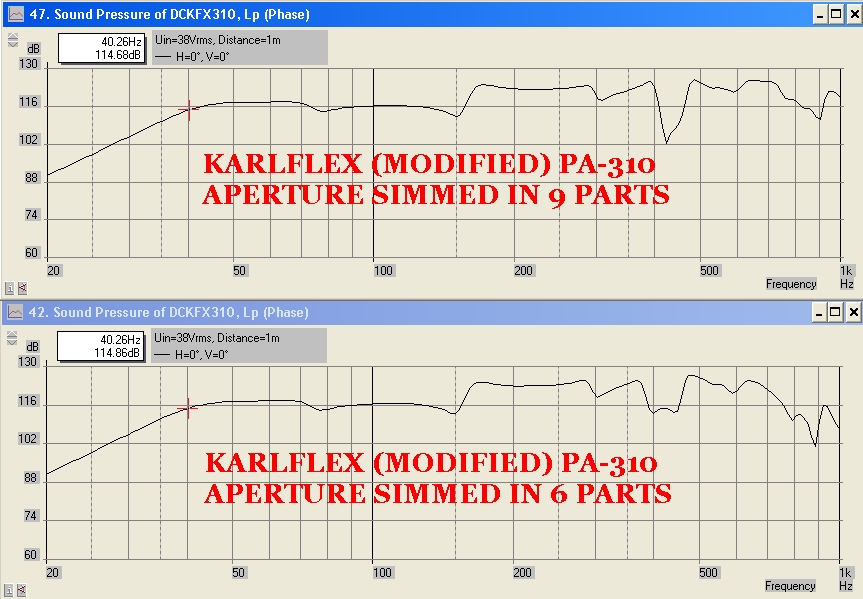
The K-aperture is in 9 parts now (9 is the minimum suggested by X), and i have them all spaced evenly ....
However, since i wanted to sim the Aperture at 60cm tall i had to divide 60 by 9 to derive the length of each part which gives me 6.66 !! Then, in order to get my coordinate placements i took 30 and divided it by 4.5 which also gives me 6.66 !!
XRK's new name is going to have to be HexRk971 !!

hehehehe
Will this speaker produce dark undertones?
Ok , now seriously , superstitious inSINuations aside
Here are the results , looks great except for the dip at 420hz ....... Needs more 420 ! .... Other than that it looks great! I still need to add the code to build out the front chamber properly and then i would imagine that the response will end up looking different than what we see here ...
Ok ,
The K-aperture is in 9 parts now (9 is the minimum suggested by X), and i have them all spaced evenly ....
However, since i wanted to sim the Aperture at 60cm tall i had to divide 60 by 9 to derive the length of each part which gives me 6.66 !!
Then, in order to get my coordinate placements i took 30 and divided it by 4.5 which also gives me 6.66 !! XRK's new name is going to have to be HexRk971 !!
hehehehe
Will this speaker produce dark undertones?
Ok , now seriously , superstitious inSINuations aside
Here are the results , looks great except for the dip at 420hz ....... Needs more 420 !
.... Other than that it looks great! I still need to add the code to build out the front chamber properly and then i would imagine that the response will end up looking different than what we see here ...Attachments

Last edited:


Ok ,
The K-aperture is in 9 parts now (9 is the minimum suggested by X), and i have them all spaced evenly ....
However, since i wanted to sim the Aperture at 60cm tall i had to divide 60 by 9 to derive the length of each part which gives me 6.66 !!
XRK's new name is going to have to be HexRk971 !!
hehehehe
Will this speaker produce dark undertones?
Ok , now seriously , superstitious inSINuations aside
Here are the results , looks great except for the dip at 420hz ....... Needs more 420 !
Nice work! I think you are the first to fully understand how I implemented a K-aperture as a series of variable sized radiators in Akabak. Are you using rectangular vent apertures or round with CSA proportional to area of rectangle? I used the rectangular ducts and radiators.
Isn't it neat that the K aperture makes the bandwidth go from 40Hz to 400Hz?
You have come a long way from this:
To this:
Last edited:
A work in progress
Thank you ! , and yessir , i think TB has a pretty good grasp of it too, in fact i think he might be a little bit ahead of me on this , i am still catching up .....
The PA-310 has the right qualities to allow a lot of upper bandwidth when loaded into one of these series tuned 6th order K boxes ...OTOH a real sub like the LAB15-4 or Alpine SWS driver won't reach as high but will create some highly respectable bass output...
I used round ducts in this sim with proportionate diameter ..... This sim (that produced the above graphs) is also a Karlflex with a twist borrowing the parasitic chamber/resonator concept from a DCR cabinet (notice the little dip at 76hz) ... Since the Karlflex already has dual chambers it would mean that adding one more makes this something like a Triple-Chamber-Karlflex or 3C-Karlflex or whatever we want to call it ..... This driver really needed better cone control since the PA310 is so excursion limited, and this was my solution ..... The box ends up being larger but i think it is a worthwhile compromise with this driver... At around 90 to 100 liters it seems to keep up with a 120 liter 40hz Tapped Horn using the same Dayton woofer with 1mm less cone movement at the same voltage drive .... The parasitic chamber requires some damping though in order to work well ... Once i have finished working through the details i will post more graphs and the script ..
The split path and extra chamber tends to ease particle velocity so that is an added bonus The impedance peak above FB also gets turned into two smaller peaks if the parasitic resonance is tuned properly ..
Thank you ! , and yessir , i think TB has a pretty good grasp of it too, in fact i think he might be a little bit ahead of me on this , i am still catching up .....
The PA-310 has the right qualities to allow a lot of upper bandwidth when loaded into one of these series tuned 6th order K boxes ...OTOH a real sub like the LAB15-4 or Alpine SWS driver won't reach as high but will create some highly respectable bass output...
I used round ducts in this sim with proportionate diameter ..... This sim (that produced the above graphs) is also a Karlflex with a twist borrowing the parasitic chamber/resonator concept from a DCR cabinet (notice the little dip at 76hz) ... Since the Karlflex already has dual chambers it would mean that adding one more makes this something like a Triple-Chamber-Karlflex or 3C-Karlflex or whatever we want to call it ..... This driver really needed better cone control since the PA310 is so excursion limited, and this was my solution ..... The box ends up being larger but i think it is a worthwhile compromise with this driver... At around 90 to 100 liters it seems to keep up with a 120 liter 40hz Tapped Horn using the same Dayton woofer with 1mm less cone movement at the same voltage drive .... The parasitic chamber requires some damping though in order to work well ... Once i have finished working through the details i will post more graphs and the script ..
The split path and extra chamber tends to ease particle velocity so that is an added bonus
The impedance peak above FB also gets turned into two smaller peaks if the parasitic resonance is tuned properly ..
Last edited:
Hi MMJ,
Sounds like you are making progress. On the raditors and radiator ducts, I would go back to the rectangular openings, the way you are doing it they should all be the same height. Together w/ the coordinates that should be more accurate.
Looking forward to seeing this latest design stage.
Regards,
Sounds like you are making progress. On the raditors and radiator ducts, I would go back to the rectangular openings, the way you are doing it they should all be the same height. Together w/ the coordinates that should be more accurate.
Looking forward to seeing this latest design stage.
Regards,
HOLY GOATS! I MADE A SCRIPT!
Ok Gentlemen, here we are ,
Project is moving along slowly but surely
This is the script for the Karlflex (triple chamber)which was modified to add a parasitic resonance around 75hz (like a DCR) which helps control excursion on this PA-310 (something the PA-310 really benefits from since it is a very capable driver electrically speaking but not physically capable in regards to linear cone travel) ..... This mod isn't necessary for many of the other drivers i would load into a Karlflex (only with lower xmax rated drivers like the PA-310) ......
*I have built out the front chamber properly (for a somewhat laid back baffle) ....
* I added height and width for all ducts (instead of diameter)
*This script also contains "Y" coordinates for the radiators ....
*K-aperture is split into 9 parts ..
* The Aperture's contour is currently questionable in this script and i may adjust it to better emulate a more traditional style Karlson contour ... Total CSA for this aperture is fairly large-ish at nearly twice the driver's SD ..
Despite this large CSA the aperture does tend to shift the FB down quite a bit , which is great news and helps to reveal our range of tunings ...
After the updates our notch in response has moved down to around 360hz , with some careful adjustment to the script i may be able to fill in that dip.
NOTE: depending on how i try to build the box i will likely replace this script's DUCT "P1" with two waveguides in order to follow the correct taper shape..
System '3C-KARLFLEX310'
Def_Driver 'PA310'
dD=30cm |Piston
fs=44.4Hz Vas=81.8L Qms=8.63
Qes=0.34 Re=5.7ohm Le=1mH ExpoLe=0.618
System 'TriChamber-KARLFLEX'
| vt=90L, v1=60L, f1=38.Hz, v2=30L, f2=46.0Hz,
|---------------------------------------------------------
| The speaker driver and the radiation from its diaphragm:
|---------------------------------------------------------
Driver 'Driver' Def='PA310' Node=1=0=10=2
|--------------------------------------------
| The first enclosure and its radiating port:
|--------------------------------------------
Duct 'P0' Node=0=2
WD=31.9cm
HD=17.6cm
Len=75.6cm
VISC=40
Duct 'P1' Node=2=3
WD=31.9cm
HD=17.6cm
Len=36.3cm
Visc=0
Duct 'P2' Node=3=4
WD=31.9cm
HD=8cm
Len=40cm
Visc=0
|Radiator 'Rad_P1' Def='P1' Node=4
|----------------------------------------------------------
| The "interchamber" port connecting the two enclosures:
|----------------------------------------------------------
Duct 'P3' Node=2=5
WD=31.9cm
HD=3cm
Len=34cm
Visc=0
|----------------------------------------------------------------------
| The second chamber or "parasitic" enclosure and its radiating port:
|-----------------------------------------------------------------------
Duct 'P4' Node=5=6 |approx 30 liter
WD=31.9cm
HD=12cm
Len=86.6cm
Visc=30
Duct 'P5' Node=6=7
WD=31.9cm
HD=3cm
Len=20cm
Visc=0
Radiator 'Rad_P5' Def='P5' Node=7
|---------------------------------------------
| The Aperture:
|(in this case the classic K-aperture,type #1)
|---------------------------------------------
| This first set of code defines the front chamber
|(behind the aperture and in front of the baffle)
| from top to bottom
|---------------------------------------------------
Duct 'P6' Node=4=8
WD=31.9cm
HD=9cm
Len=6.66cm
Visc=0
Duct 'P7' Node=8=9
WD=31.9cm
HD=8cm
Len=6.66cm
Visc=0
Duct 'P8' Node=9=10
WD=31.9cm
HD=7cm
Len=6.66cm
Visc=0
Duct 'P9' Node=10=11
WD=31.9cm
HD=6cm
Len=6.66cm
Visc=0
Duct 'P10' Node=11=12
WD=31.9cm
HD=5cm
Len=6.66cm
Visc=0
Duct 'P11' Node=12=13
WD=31.9cm
HD=4cm
Len=6.66cm
Visc=0
Duct 'P12' Node=13=14
WD=31.9cm
HD=3cm
Len=6.66cm
Visc=0
Duct 'P13' Node=14=15
WD=31.9cm
HD=2cm
Len=6.66cm
Visc=0
Duct 'P14' Node=15=16
WD=31.9cm
HD=1cm
Len=6.66cm
Visc=0
|--------------------------------------------------------------------
|The following code defines the dadiators (K-aperture in multiple parts)
| series tuned
|--------------------------------------------------------------------
Radiator 'Rad_P6' Node=8 |CSA=19.98sq cm
WD=3cm
HD=6.66cm
x=0 y=28cm z=0 HAngle=0 VAngle=0
Radiator 'Rad_P7' Node=9 |CSA=26.64sq cm
WD=4cm
HD=6.66cm
x=0 y=21.33cm z=0 HAngle=0 VAngle=0
Radiator 'Rad_P8' Node=10 |CSA=39.96sq cm
WD=6cm
HD=6.66cm
x=0 y=15cm z=0 HAngle=0 VAngle=0
Radiator 'Rad_P9' Node=11 |CSA=66.66sq cm
WD=10cm
HD=6.66cm
x=0 y=8.33cm z=0 HAngle=0 VAngle=0
Radiator 'Rad_P10' Node=12 |CSA=93.24sq cm
WD=14cm
HD=6.66cm
x=0 y=0 z=0 HAngle=0 VAngle=0
Radiator 'Rad_P11' Node=13 |CSA=119.88sq cm
WD=18cm
HD=6.66cm
x=0 y=-8.33cm z=0 HAngle=0 VAngle=0
Radiator 'Rad_P12' Node=14 |CSA=159.84sq cm
WD=24cm
HD=6.66cm
x=0 y=-15cm z=0 HAngle=0 VAngle=0
Radiator 'Rad_P13' Node=15 |CSA=186.48sq cm
WD=28cm
HD=6.66cm
x=0 y=-21.33cm z=0 HAngle=0 VAngle=0
Radiator 'Rad_P14' Node=16 |CSA=212.454sq cm
WD=31.9cm
HD=6.66cm
x=0 y=-28cm z=0 HAngle=0 VAngle=0
|Total Aperture CSA=925.134sq cm
Ok Gentlemen, here we are ,
Project is moving along slowly but surely
This is the script for the Karlflex (triple chamber)
which was modified to add a parasitic resonance around 75hz (like a DCR) which helps control excursion on this PA-310 (something the PA-310 really benefits from since it is a very capable driver electrically speaking but not physically capable in regards to linear cone travel) ..... This mod isn't necessary for many of the other drivers i would load into a Karlflex (only with lower xmax rated drivers like the PA-310) ......*I have built out the front chamber properly (for a somewhat laid back baffle) ....
* I added height and width for all ducts (instead of diameter)
*This script also contains "Y" coordinates for the radiators ....
*K-aperture is split into 9 parts ..
* The Aperture's contour is currently questionable in this script
and i may adjust it to better emulate a more traditional style Karlson contour ... Total CSA for this aperture is fairly large-ish at nearly twice the driver's SD .. Despite this large CSA the aperture does tend to shift the FB down quite a bit , which is great news and helps to reveal our range of tunings ...
After the updates our notch in response has moved down to around 360hz , with some careful adjustment to the script i may be able to fill in that dip.
NOTE: depending on how i try to build the box i will likely replace this script's DUCT "P1" with two waveguides in order to follow the correct taper shape..
System '3C-KARLFLEX310'
Def_Driver 'PA310'
dD=30cm |Piston
fs=44.4Hz Vas=81.8L Qms=8.63
Qes=0.34 Re=5.7ohm Le=1mH ExpoLe=0.618
System 'TriChamber-KARLFLEX'
| vt=90L, v1=60L, f1=38.Hz, v2=30L, f2=46.0Hz,
|---------------------------------------------------------
| The speaker driver and the radiation from its diaphragm:
|---------------------------------------------------------
Driver 'Driver' Def='PA310' Node=1=0=10=2
|--------------------------------------------
| The first enclosure and its radiating port:
|--------------------------------------------
Duct 'P0' Node=0=2
WD=31.9cm
HD=17.6cm
Len=75.6cm
VISC=40
Duct 'P1' Node=2=3
WD=31.9cm
HD=17.6cm
Len=36.3cm
Visc=0
Duct 'P2' Node=3=4
WD=31.9cm
HD=8cm
Len=40cm
Visc=0
|Radiator 'Rad_P1' Def='P1' Node=4
|----------------------------------------------------------
| The "interchamber" port connecting the two enclosures:
|----------------------------------------------------------
Duct 'P3' Node=2=5
WD=31.9cm
HD=3cm
Len=34cm
Visc=0
|----------------------------------------------------------------------
| The second chamber or "parasitic" enclosure and its radiating port:
|-----------------------------------------------------------------------
Duct 'P4' Node=5=6 |approx 30 liter
WD=31.9cm
HD=12cm
Len=86.6cm
Visc=30
Duct 'P5' Node=6=7
WD=31.9cm
HD=3cm
Len=20cm
Visc=0
Radiator 'Rad_P5' Def='P5' Node=7
|---------------------------------------------
| The Aperture:
|(in this case the classic K-aperture,type #1)
|---------------------------------------------
| This first set of code defines the front chamber
|(behind the aperture and in front of the baffle)
| from top to bottom
|---------------------------------------------------
Duct 'P6' Node=4=8
WD=31.9cm
HD=9cm
Len=6.66cm
Visc=0
Duct 'P7' Node=8=9
WD=31.9cm
HD=8cm
Len=6.66cm
Visc=0
Duct 'P8' Node=9=10
WD=31.9cm
HD=7cm
Len=6.66cm
Visc=0
Duct 'P9' Node=10=11
WD=31.9cm
HD=6cm
Len=6.66cm
Visc=0
Duct 'P10' Node=11=12
WD=31.9cm
HD=5cm
Len=6.66cm
Visc=0
Duct 'P11' Node=12=13
WD=31.9cm
HD=4cm
Len=6.66cm
Visc=0
Duct 'P12' Node=13=14
WD=31.9cm
HD=3cm
Len=6.66cm
Visc=0
Duct 'P13' Node=14=15
WD=31.9cm
HD=2cm
Len=6.66cm
Visc=0
Duct 'P14' Node=15=16
WD=31.9cm
HD=1cm
Len=6.66cm
Visc=0
|--------------------------------------------------------------------
|The following code defines the dadiators (K-aperture in multiple parts)
| series tuned
|--------------------------------------------------------------------
Radiator 'Rad_P6' Node=8 |CSA=19.98sq cm
WD=3cm
HD=6.66cm
x=0 y=28cm z=0 HAngle=0 VAngle=0
Radiator 'Rad_P7' Node=9 |CSA=26.64sq cm
WD=4cm
HD=6.66cm
x=0 y=21.33cm z=0 HAngle=0 VAngle=0
Radiator 'Rad_P8' Node=10 |CSA=39.96sq cm
WD=6cm
HD=6.66cm
x=0 y=15cm z=0 HAngle=0 VAngle=0
Radiator 'Rad_P9' Node=11 |CSA=66.66sq cm
WD=10cm
HD=6.66cm
x=0 y=8.33cm z=0 HAngle=0 VAngle=0
Radiator 'Rad_P10' Node=12 |CSA=93.24sq cm
WD=14cm
HD=6.66cm
x=0 y=0 z=0 HAngle=0 VAngle=0
Radiator 'Rad_P11' Node=13 |CSA=119.88sq cm
WD=18cm
HD=6.66cm
x=0 y=-8.33cm z=0 HAngle=0 VAngle=0
Radiator 'Rad_P12' Node=14 |CSA=159.84sq cm
WD=24cm
HD=6.66cm
x=0 y=-15cm z=0 HAngle=0 VAngle=0
Radiator 'Rad_P13' Node=15 |CSA=186.48sq cm
WD=28cm
HD=6.66cm
x=0 y=-21.33cm z=0 HAngle=0 VAngle=0
Radiator 'Rad_P14' Node=16 |CSA=212.454sq cm
WD=31.9cm
HD=6.66cm
x=0 y=-28cm z=0 HAngle=0 VAngle=0
|Total Aperture CSA=925.134sq cm
Attachments


Last edited:
MMJ,
Fantastic work! Don't you just love the infinite possibilities of what Akabak can do? Need a parasitic chamber? No problem! Need a variable aperture? No problem! This is really a great leap of simulation capability that you have just taught yourself. Regarding following the Karlson aperture profile: look back at my Karlson posts and I gave the quadratic curve fit of the aperture width vs distance from the top cusp. The equation needs to be normalized so that at unit length 1 the aperture is 1. Then use this to scale whatever width and height of the K aperture you put in. This automatically provides the width of each K aperture duct and radiator as well as its y offset.
Another tip for readability of graphs: in edit menu there is a copy as bitmap option. This lets you save high res images of your plot wondows (which you can expand on screen to appropriate size).
Also when posting script, post it into the insert code button (#) at top. So that long scripts appear more compact for people browsing thread - also code is in courier which is easier to read.
Thanks for your efforts and for sharing.
Edit
Thanks guys!
I would not have been able to do this without all of you guiding me through it ..
I did spot a mistake already ... In order to fix it I just needed to move the woofer's front-of-cone node to the right spot so it correlates with the correct placement of the driver, which is just about halfway up the baffle using this amount of offset ... I also took the time to adjust the K-aperture contour ... The aperture has less total CSA now.... After these changes the dip around 350hz is not quite as extreme ...
Here is the corrected script (i will try to post it in the way X suggested):
System '3C-KARLFLEX310'
Def_Driver 'PA310'
dD=30cm |Piston
fs=44.4Hz Vas=81.8L Qms=8.63
Qes=0.34 Re=5.7ohm Le=1mH ExpoLe=0.618
System 'TriChamber-KARLFLEX'
| vt=90L, v1=60L, f1=38.Hz, v2=30L, f2=46.0Hz,
|---------------------------------------------------------
| The speaker driver and the radiation from its diaphragm:
|---------------------------------------------------------
Driver 'Driver' Def='PA310' Node=1=0=12=2
|--------------------------------------------
| The first enclosure and its radiating port:
|--------------------------------------------
Duct 'P0' Node=0=2
WD=31.9cm
HD=17.6cm
Len=77.6cm
VISC=40
Duct 'P1' Node=2=3
WD=31.9cm
HD=17.6cm
Len=34.3cm
Visc=0
Duct 'P2' Node=3=4
WD=31.9cm
HD=8cm
Len=40cm
Visc=0
|----------------------------------------------------------
| The "interchamber" port connecting the two enclosures:
|----------------------------------------------------------
Duct 'P3' Node=2=5
WD=31.9cm
HD=3cm
Len=34cm
Visc=0
|----------------------------------------------------------------------
| The second chamber or "parasitic" enclosure and its radiating port:
|-----------------------------------------------------------------------
Duct 'P4' Node=5=6 |approx 30 liter
WD=31.9cm
HD=12cm
Len=86.6cm
Visc=30
Duct 'P5' Node=6=7
WD=31.9cm
HD=3cm
Len=20cm
Visc=0
Radiator 'Rad_P5' Def='P5' Node=7
x=0 y=-40cm z=0 HAngle=0 VAngle=0
|---------------------------------------------
| The Aperture:
|(in this case the classic K-aperture,type #1)
|---------------------------------------------
| This first set of code defines the front chamber
|(behind the aperture and in front of the baffle)
| from top to bottom
|---------------------------------------------------
Duct 'P6' Node=4=8
WD=31.9cm
HD=9cm
Len=6.66cm
Visc=0
Duct 'P7' Node=8=9
WD=31.9cm
HD=8cm
Len=6.66cm
Visc=0
Duct 'P8' Node=9=10
WD=31.9cm
HD=7cm
Len=6.66cm
Visc=0
Duct 'P9' Node=10=11
WD=31.9cm
HD=6cm
Len=6.66cm
Visc=0
Duct 'P10' Node=11=12
WD=31.9cm
HD=5cm
Len=6.66cm
Visc=0
Duct 'P11' Node=12=13
WD=31.9cm
HD=4cm
Len=6.66cm
Visc=0
Duct 'P12' Node=13=14
WD=31.9cm
HD=3cm
Len=6.66cm
Visc=0
Duct 'P13' Node=14=15
WD=31.9cm
HD=2cm
Len=6.66cm
Visc=0
Duct 'P14' Node=15=16
WD=31.9cm
HD=1cm
Len=6.66cm
Visc=0
|--------------------------------------------------------------------
|The following code defines the dadiators (K-aperture in multiple parts)
| series tuned
|--------------------------------------------------------------------
Radiator 'Rad_P6' Node=8 |CSA=19.98sq cm
WD=3cm
HD=6.66cm
x=0 y=28cm z=0 HAngle=0 VAngle=0
Radiator 'Rad_P7' Node=9 |CSA=26.64sq cm
WD=4cm
HD=6.66cm
x=0 y=21.33cm z=0 HAngle=0 VAngle=0
Radiator 'Rad_P8' Node=10 |CSA=33.3sq cm
WD=5cm
HD=6.66cm
x=0 y=15cm z=0 HAngle=0 VAngle=0
Radiator 'Rad_P9' Node=11 |CSA=39.96sq cm
WD=6cm
HD=6.66cm
x=0 y=8.33cm z=0 HAngle=0 VAngle=0
Radiator 'Rad_P10' Node=12 |CSA=66.6sq cm
WD=10cm
HD=6.66cm
x=0 y=0 z=0 HAngle=0 VAngle=0
Radiator 'Rad_P11' Node=13 |CSA=119.88sq cm
WD=18cm
HD=6.66cm
x=0 y=-8.33cm z=0 HAngle=0 VAngle=0
Radiator 'Rad_P12' Node=14 |CSA=159.84sq cm
WD=24cm
HD=6.66cm
x=0 y=-15cm z=0 HAngle=0 VAngle=0
Radiator 'Rad_P13' Node=15 |CSA=186.48sq cm
WD=28cm
HD=6.66cm
x=0 y=-21.33cm z=0 HAngle=0 VAngle=0
Radiator 'Rad_P14' Node=16 |CSA=212.454sq cm
WD=31.9cm
HD=6.66cm
x=0 y=-28cm z=0 HAngle=0 VAngle=0
|Total Aperture CSA=865.134sq cm
Attachments

Last edited:
Ok Gentlemen, here we are ,
Project is moving along slowly but surely
This is the script for the Karlflex (triple chamber)
Just a couple of notes - as I mentioned, it's a lot easier if you start in Hornresp, let that generate the script, and finish in Akabak. Hornresp could have given you the first half of that box in about 3 minutes of work and you could have just exported and added to that. There's nothing wrong with writing the script from scratch in Akabak but there are several advantages to not doing that. Saves time, ensures accuracy (no schematic in Akabak), etc.
Second, there are 23 db between the lines in the sim you showed. Even a 10 db bump will look pretty smooth at that resolution. Within a sub's passband your response is fairly smooth anyway, there's nothing to hide, so it's common practice to zoom in to a higher resolution and show no more than 5 db between the lines like Hornresp. Some people zoom in closer than that even.
Not sure what nodes are what and I don't have time to figure it out. Did you check velocity at the pinch points? What's the velocity at the mouth?
I told you Akabak was the way to go for these things. There's really no way to get accurate sims of the stuff you want to do without it. (ABEC maybe but no other software can do these and guessing with Hornresp just doesn't cut it).
a tiny hop at best or maybe a slow shuffle =P
Hehehe ,
I hope it is at least some kind of small progress
Freddi, Has anyone ever made a triple chamber Karlson box with parasitic chamber/resonator? I know you are highly knowledgeable on the topic of K cabs , so i am sure you would have heard about it if there ever was such a thing ....
I also just figured out an elegant adjustment that can be made to the Karlflex boxes that will generate the same response as the weird "invert aperture" (or semi-invert/semi-parallel tuned) concept , but while still having a traditionally oriented K-aperture that is series tuned like the Karlsonator or XKi ........ It is all just a matter of changing dimensions of the S1 stub section ( the portion of path before the driver or offset) , and it basically works by increasing damping (and midband response) if that section is made longer (more offset) with less CSA , and vice-versa for a driver that has a lack of motor strength and doesn't require a lift in midband output ..... There is even a "happy medium" which is suitable for a wide range of drivers ...... TB46's recent iteration of the Karlflex inspired me to experiment with this idea .... I think i may have come up with a very simple change to the fold too , but i am still tinkering with it in HR , once i transfer it over to Akabak and slap the aperture onto the front i will be sure to post it here if everything measures well .... If this idea does work then it will be more universal than previous versions with less customizing required to suit particular drivers ....
a giant leap in Karlsonology !
Hehehe ,
I hope it is at least some kind of small progress
Freddi, Has anyone ever made a triple chamber Karlson box with parasitic chamber/resonator? I know you are highly knowledgeable on the topic of K cabs , so i am sure you would have heard about it if there ever was such a thing ....
I also just figured out an elegant adjustment that can be made to the Karlflex boxes that will generate the same response as the weird "invert aperture" (or semi-invert/semi-parallel tuned) concept , but while still having a traditionally oriented K-aperture that is series tuned like the Karlsonator or XKi ........ It is all just a matter of changing dimensions of the S1 stub section ( the portion of path before the driver or offset) , and it basically works by increasing damping (and midband response) if that section is made longer (more offset) with less CSA , and vice-versa for a driver that has a lack of motor strength and doesn't require a lift in midband output ..... There is even a "happy medium" which is suitable for a wide range of drivers ...... TB46's recent iteration of the Karlflex inspired me to experiment with this idea .... I think i may have come up with a very simple change to the fold too , but i am still tinkering with it in HR , once i transfer it over to Akabak and slap the aperture onto the front i will be sure to post it here if everything measures well
.... If this idea does work then it will be more universal than previous versions with less customizing required to suit particular drivers ....
Last edited:
no - -never seen a parasitic section - - if you are playing this at lower levels then a 5.3" K-tube on a modest ("cheap") one inch format compression driver may make a cool 2-way system. Do you think PA310 can wiggle up to 1K5?
http://a.imageshack.us/img829/7172/speedking.jpg
http://home.planet.nl/~ulfman/images/soundl12.jpg
http://a.imageshack.us/img829/7172/speedking.jpg
http://home.planet.nl/~ulfman/images/soundl12.jpg
An externally hosted image should be here but it was not working when we last tested it.
Last edited:
Just a couple of notes - as I mentioned, it's a lot easier if you start in Hornresp, let that generate the script, and finish in Akabak. Hornresp could have given you the first half of that box in about 3 minutes of work and you could have just exported and added to that. There's nothing wrong with writing the script from scratch in Akabak but there are several advantages to not doing that. Saves time, ensures accuracy (no schematic in Akabak), etc.
JAG,
Right , starting off with HR would be fast and effective, but in this case i just modified the heck out of (and built upon) a DCR script that someone posted elsewhere in some Akabak tutorial ...
Second, there are 23 db between the lines in the sim you showed. Even a 10 db bump will look pretty smooth at that resolution. Within a sub's passband your response is fairly smooth anyway, there's nothing to hide, so it's common practice to zoom in to a higher resolution and show no more than 5 db between the lines like Hornresp. Some people zoom in closer than that even.
I was attempting to fit three graphs onto a single easily viewable image without the need for scrolling , so that was the reason for the graph proportions , and right , not too much to hide there really, bandwidth looks pretty good out to at least 260hz , might even be useable to 330 .... I would like to improve the range between 300 and 400 , and mayhaps as i fix the contour of the aperture that will happen, but if not i am still happy with that sort of bandwidth from a 40hz tuned bandpass box
Not sure what nodes are what and I don't have time to figure it out. Did you check velocity at the pinch points? What's the velocity at the mouth?
I told you Akabak was the way to go for these things. There's really no way to get accurate sims of the stuff you want to do without it. (ABEC maybe but no other software can do these and guessing with Hornresp just doesn't cut it).
Yessir, take a look at the bottom graph from the attachment in post #1233 .... Those are the velocities from the points of greatest constriction in the cabinet , nothing exceeds 13 m/s at 38v ......Being set-up like a DCR gives this cabinet a split path, which can ease the air flow as part of the flow is directed through the parasitic chamber/radiator section........The velocity at the mouth is very low because the mouth's area is even larger than the driver's SD .....
I am loving Akabak so far, i love the freedom if it, and the ability to basically add as many components as you will ever need and arrange them in any manner you like.
Last edited:
no - -never seen a parasitic section - - if you are playing this at lower levels then a 5.3" K-tube on a modest ("cheap") one inch format compression driver may make a cool 2-way system. Do you think PA310 can wiggle up to 1K5?
http://a.imageshack.us/img829/7172/speedking.jpg
http://home.planet.nl/~ulfman/images/soundl12.jpg
Freddi,
Not sure how high the bandwidth of the cabinet will actually extend ... I will get measurements once built ... At these power levels (38v with the Pa-310) im sure a person could just mount a sealed-back mid into one of the aperture wings (if necessary) to get your response up to where it meets the tweet ... Could make a nice three-way cab.
ps: Love your second link "SOUND LASERS"!! hahaha thats awesome !
Matthew,
I have been following this thread for quite a while and scratching my head as to just what exactly the constriction or pinch point actually accomplishes.
Recently the thought has come to mind that 2 chambers with a constricted connection between them, in the path of the driver back wave, may cause a phase shift in the pressure wave between the chambers
Is it possible that a phase shift here could act the same way as a longer path length, causing the back wave to reunite with the front wave at a lower frequency, thus making the path seem longer (lower frequency).
In other words providing lower extension or the same LF extension in a smaller cabinet.
I could be all wet here, and was wondering if I am anywhere near to reality.
Keep up the good work,
Dave
- Status
- This old topic is closed. If you want to reopen this topic, contact a moderator using the "Report Post" button.
- Home
- Loudspeakers
- Subwoofers
- New sub design? Constricted Transflex, simple build (series tuned 6th order)