the original Karlson cabinet (finished in the summer of 1951) plays pretty clean - moreso than some horn cabinets. I purchased a Yorkville USC1 and ran a few sine tests of it vs a one sheet K-type tuned with two 4" id ducts (not flared) - USC1 had 20dB more H2 at only 20vrms. This K-type wasn't as smooth as K15 which had a reflective front board. The rear section of K15's board acted as a mild choke and filter.
when K15 was subjectively compared to a 3.6 cubic foot reflex tuned to around 50Hz and driven at 36Hz/20vrms, the Karlson rectangular vent and main aperture had a lot less chuffing than the reflex and less cone excursion. K15 in its upper front chamber has ~Sd CSA IIRC so is not 'pinched".
I think I could take a K12 of the distributed slit vent variety and play bass guitar into it and the listener would not perceive any pitch shift or distortion - but if I ran sine at say 60Hz and 1 watt level into the same cabinet, there would be distortion stronger than the fundamental (F3 is higher than 60) and a series of (loud) harmonics extending way up. It would blow out a candle a foot away from the aperture at 1 watt. A single 10 or so sq.in. vent would fix the sine distortion. If a given regular coupled-cavity K-type with a single or double vent subjectively sounds somewhat heavy/'thick" then a few small holes added to the reflector wil make the sound "faster". (crazy subjective stuff)
how does music type and instrument type matter with regards to subjective bass distortion? when does music approach sine conditions? I would assume a classical jazz trio of upright bass, acoustic drumkit and piano to be different than some synthesized modern bass which may have some reasonably pure sine sweeps within.
it'll be real interesting to see Akabak simulations of MMJ's proposals.
Freddi ,
Based upon what you have said above it again makes me wonder if there might be something special going on in the K-arrangement which makes it's internal vent less prone to chuffing ..... The discount in velocity due to the port being buried inside of the path is probably not enough (alone) to account for the stark contrast you observed between The Karlson and Yorkville cabinets you mentioned above ...... JAG would likely just attribute it to "masking", but is it possible that there is some other phenomenon factoring into this equation? .....
I think that a way to test this would be to construct two cabinets of the same size and tuning (and not too low) for use with a high excursion driver, one would be a Karlson variant (like a Karlsonator), and the other would be a typical bass-reflex but both would use the same intentionally undersized non-flared ports with equal CSA .....
When taking measurements of both cabinets using pink noise or sine sweeps at both high and low power levels as a deliberate attempt to induce measurable port compression I suspect that the K-variant would have 10% to 20% less port compression (if my HR experiment using "buried" vents is remotely accurate) but if the discrepancy between the two cabinets were to extend beyond 20% near FB (where the velocity peak is) then we would have to conclude that something extraordinary is taking place ... Something that we haven't yet taken into account ...
as a guess, just cutting a K-slot into an arbitrary design without some thought may do more harm than good.
K15 is well behaved. If a mic is placed near the center of the cone, there's a null around 36Hz - a half octave below its nominal tuning. In contrast, K12 with slit vents distorts quite a bit on sine. Here's an in-room comparison (speaker and mic position fixed) of a slit vent K12 with pym1298 vs a Karlsonette copy with a K15 position single vent and Beta 12LTA. You can see the additional distortion at this low drive level. In practice, the 80oz magnet woofer sounds punchier imo than the wideband - plus I think the pym/kappa12 design has more real xmax than the wideband which claims large xmax but only has 0.08" overhang and a little motor.
32Hz was over an octave below K12's LF corner. Driving at 60-70Hz would
really turn on the slit vent distortion - but with a lot of music I like, would not be noticed
as "distortion"

a one sheet K-type with an Eminence 18 - for this test, I had two 4" ducts installed as the vent - note the big first dip - K15 is better in this area, and other couplers might do better too without the front shelf - I think dimensions in the front chamber matter - I normally ran this coupler tuned higher with two 4.5" holes in the divider.
simple K-box with Eminence 18 vs a new Yorkville USC1 11 cubic foot sub woofer - mic distance 6M, drive 20vrms - I was not happy to spend so much to get 20dB more H2 from the USC1
here's a weak motor Beta15cx - low mass many rib cone - in K15 and in a reflex with Fb ~50Hz the size of K15's rear chamber - - look at the reduction of sidebands. A reflex the total size of K15 could be tuned to go lower have more output - the K has less cone movement, somewhat more output. Perhaps a fair test would be to look at two tone modulation on the musical scale with fundamental at 41Hz start for stuff based on E-tuned 4-string basses.
K15's trace would have looked even better if I had remembered to shut off a far away window air conditioner. PWK made fun of Karlson's claims - after owning two sets of Klipschorns and many Karlsons, I think K15 offered better sound depending upon what the listener concentrated upon. Some horns mate well with K15 - some don't.
K15 is well behaved. If a mic is placed near the center of the cone, there's a null around 36Hz - a half octave below its nominal tuning. In contrast, K12 with slit vents distorts quite a bit on sine. Here's an in-room comparison (speaker and mic position fixed) of a slit vent K12 with pym1298 vs a Karlsonette copy with a K15 position single vent and Beta 12LTA. You can see the additional distortion at this low drive level. In practice, the 80oz magnet woofer sounds punchier imo than the wideband - plus I think the pym/kappa12 design has more real xmax than the wideband which claims large xmax but only has 0.08" overhang and a little motor.
32Hz was over an octave below K12's LF corner. Driving at 60-70Hz would
really turn on the slit vent distortion - but with a lot of music I like, would not be noticed
as "distortion"
a one sheet K-type with an Eminence 18 - for this test, I had two 4" ducts installed as the vent - note the big first dip - K15 is better in this area, and other couplers might do better too without the front shelf - I think dimensions in the front chamber matter - I normally ran this coupler tuned higher with two 4.5" holes in the divider.
simple K-box with Eminence 18 vs a new Yorkville USC1 11 cubic foot sub woofer - mic distance 6M, drive 20vrms - I was not happy to spend so much to get 20dB more H2 from the USC1
An externally hosted image should be here but it was not working when we last tested it.
here's a weak motor Beta15cx - low mass many rib cone - in K15 and in a reflex with Fb ~50Hz the size of K15's rear chamber - - look at the reduction of sidebands. A reflex the total size of K15 could be tuned to go lower have more output - the K has less cone movement, somewhat more output. Perhaps a fair test would be to look at two tone modulation on the musical scale with fundamental at 41Hz start for stuff based on E-tuned 4-string basses.
K15's trace would have looked even better if I had remembered to shut off a far away window air conditioner. PWK made fun of Karlson's claims - after owning two sets of Klipschorns and many Karlsons, I think K15 offered better sound depending upon what the listener concentrated upon. Some horns mate well with K15 - some don't.
An externally hosted image should be here but it was not working when we last tested it.
Last edited:
For breakfast we are having distortion and maple syrup , dark amber , grade B
FREDDI ,
Hey now , these are some very INTERESTING graphs! ....

Actual measurements which make this data much better than just any ole subjective reports and certainly more useful to even the most discriminating of Canadians!") hehehehehehehe (just kidding around, "discriminating" is a good thing, and I love our neighbors to the north, and they should love me too with the amount of maple syrup i buy at this house, like a huge damn bottle every week because we sweeten all sorts of foods and drinks with it, great stuff!! .......I'm serious now ..... Maple syrup is VERY expensive down here in the desert, but i make the sacrifice and buy it anyway, because it is THAT heavenly!
hehehehehehehe (just kidding around, "discriminating" is a good thing, and I love our neighbors to the north, and they should love me too with the amount of maple syrup i buy at this house, like a huge damn bottle every week because we sweeten all sorts of foods and drinks with it, great stuff!! .......I'm serious now ..... Maple syrup is VERY expensive down here in the desert, but i make the sacrifice and buy it anyway, because it is THAT heavenly!  ) ............
Ok , anyway , back on track now
Freddi,
In the second graph down the K-cabinet's harmonic distortion is 20db-ish below the Yorkville sub at the second harmonic !! Very noteworthy!
Since the second harmonic is placed well below the bandpass cutoff for that K cabinet we cannot really attribute such cleanliness to any masking effect at that frequency, so something else is going on there .......
I also noticed that there is also a weird little non-harmonic blip centered around 80hz on the Yorkville , not very loud but what do you suppose that is? A cabinet or panel resonance maybe? (even though it is miniscule) That blip it may indicate a problem, a design flaw perhaps ...
The lack of sidebanding with the K-Cab two-tone test comparison in the last graph is also highly interesting! ....Once again this cannot be attributed to masking since the 160hz output from the K-cab does not look suppressed at all (meaning the bandpass cutoff on that box is above 160hz), yet those unsavory sidebands are clearly suppressed for some reason...... Is it possible that the improved cone control of the K-cabinets helps to reduce harmonic distortion and sidebanding?
Is there a current theory about how this works Freddi?
The signal stays intact while the undesirable bits are suppressed Seems almost too good to be true
However, on the other hand, regarding that old multi-slotted vent (was that supposed to be the Q-lowering vent technology?) , it would not be appropriate with modern music because of all of the sines and tremendous low frequency energy in modern popular recordings so i would never consider using the multi-slot vent with a full mix or as a sub but i definitely think that musicians may have a use for a high distortion design like that in order to amp & mic individual instruments and add an artistic harmonically rich effect to the sound with things like a some guitars, bass guitars, synths or anything else that you might want to add some organic sounding harmonic grunge effect to ...
FREDDI ,
Hey now , these are some very INTERESTING graphs! ....
Actual measurements which make this data much better than just any ole subjective reports and certainly more useful to even the most discriminating of Canadians!
hehehehehehehe (just kidding around, "discriminating" is a good thing, and I love our neighbors to the north, and they should love me too with the amount of maple syrup i buy at this house, like a huge damn bottle every week because we sweeten all sorts of foods and drinks with it, great stuff!! .......I'm serious now ..... Maple syrup is VERY expensive down here in the desert, but i make the sacrifice and buy it anyway, because it is THAT heavenly! ) ............Ok , anyway , back on track now
Freddi,
In the second graph down the K-cabinet's harmonic distortion is 20db-ish below the Yorkville sub at the second harmonic !! Very noteworthy!
Since the second harmonic is placed well below the bandpass cutoff for that K cabinet we cannot really attribute such cleanliness to any masking effect at that frequency, so something else is going on there .......
I also noticed that there is also a weird little non-harmonic blip centered around 80hz on the Yorkville , not very loud but what do you suppose that is? A cabinet or panel resonance maybe? (even though it is miniscule) That blip it may indicate a problem, a design flaw perhaps ...
The lack of sidebanding with the K-Cab two-tone test comparison in the last graph is also highly interesting! ....Once again this cannot be attributed to masking since the 160hz output from the K-cab does not look suppressed at all (meaning the bandpass cutoff on that box is above 160hz), yet those unsavory sidebands are clearly suppressed for some reason...... Is it possible that the improved cone control of the K-cabinets helps to reduce harmonic distortion and sidebanding?
Is there a current theory about how this works Freddi?
The signal stays intact while the undesirable bits are suppressed
Seems almost too good to be true However, on the other hand, regarding that old multi-slotted vent (was that supposed to be the Q-lowering vent technology?) , it would not be appropriate with modern music because of all of the sines and tremendous low frequency energy in modern popular recordings so i would never consider using the multi-slot vent with a full mix or as a sub but i definitely think that musicians may have a use for a high distortion design like that in order to amp & mic individual instruments and add an artistic harmonically rich effect to the sound with things like a some guitars, bass guitars, synths or anything else that you might want to add some organic sounding harmonic grunge effect to ...
I fully agree .... You are referring to the K-cab vs reflex port compression test right? .... It would take two properly calculated and well built boxes with the same tuning , same size , same driver , same vent CSA etc , just to make things fair ... I suggested the Karlsonator to represent the K-cabs because i know it is a well tested design at this point and it can be tuned low ... You suggested a two tone test with 41hz fundamental so perhaps a 40hz tuning on the cabs .... Do you suppose a K15 would be a better choice for this sort of test?As a guess, just cutting a K-slot into an arbitrary design without some thought may do more harm than good.
Last edited:
I had fresh JBL M151 in a K15 vs 3.6 cubic foot reflex - the reflex was tuned with two 4" ID pvc non-flared ducts and chuffed "a lot" more than than the Karlson K15 which had a 30.5 sq.in. by 3/4" deep rectangular vent. I'm too old to go back and do the tests outdoors - it matters little . The best thing perhaps for this thread is to get a new cabinet of your design up and running then examine how it does vs something similar in size and purpose plus see how close actual measurements come to hornresp and Akabak sims.
the time of the slit vent K12 was around 1956 - music peddled in those days might include Martin Denny, folk singers, blues singers, Dixieland/"ragtime, classical new and re-issues - not much sine "bass-bath" material. Enclosures in those days were sold without drivers, besides a faddish introduction of distributive ports, it may have been believed that they allowed more drivers including those with small magnets to work. Distributed hissy vents could "sound better" with some music genre ;^) - they have power input variable input Z and drag - I heard little problem with slit vent K12 on drums with 200 watt input peaks.
the time of the slit vent K12 was around 1956 - music peddled in those days might include Martin Denny, folk singers, blues singers, Dixieland/"ragtime, classical new and re-issues - not much sine "bass-bath" material. Enclosures in those days were sold without drivers, besides a faddish introduction of distributive ports, it may have been believed that they allowed more drivers including those with small magnets to work. Distributed hissy vents could "sound better" with some music genre ;^) - they have power input variable input Z and drag - I heard little problem with slit vent K12 on drums with 200 watt input peaks.
Last edited:
oodles and gobs
Freddi,
Good to hear! An experience where you had more chuffing with a Bass reflex than you had with a K-cab with the same driver ..... Brings up the question of masking again or the possibility that Mr Karlson was onto something very special with his designs ...
Did you happen to get response measurements on those JBL loaded cabs for the sake of comparison?
Yessir, that is the plan, drivers will arrive in a few days, then to get ply and make sawdust! =D
I have a Dayton measurement mic, an install of HolmImpulse, and the DATS unit so i can generate response and impedance charts etc ... ...
Bygone eras with such substance and soul !!!! ........... So the distributed slot vent made that box more compatible with a very wide range of driver parameters? I suppose that would make sense if cabinets were sold without drivers in those days, people would be loading all sorts of random woofers into it .......
By the way , an instrument being played through an overdriven tube amp and into your slot-vented K12 would just have oodles and gobs of wonderful saturated vintage personality and character and could be great for studio work because it is difficult to properly emulate that sort of sound in software ...
I had fresh JBL M151 in a K15 vs 3.6 cubic foot reflex - the reflex was tuned with two 4" ID pvc non-flared ducts and chuffed "a lot" more than than the Karlson K15 which had a 30.5 sq.in. by 3/4" deep rectangular vent. I'm too old to go back and do the tests outdoors - it matters little .
Freddi,
Good to hear! An experience where you had more chuffing with a Bass reflex than you had with a K-cab with the same driver ..... Brings up the question of masking again or the possibility that Mr Karlson was onto something very special with his designs ...
Did you happen to get response measurements on those JBL loaded cabs for the sake of comparison?
The best thing perhaps for this thread is to get a new cabinet of your design up and running
Yessir, that is the plan, drivers will arrive in a few days, then to get ply and make sawdust! =D
I have a Dayton measurement mic, an install of HolmImpulse, and the DATS unit so i can generate response and impedance charts etc ... ...
the time of the slit vent K12 was around 1956 - music peddled in those days might include Martin Denny, folk singers, blues singers, Dixieland/"ragtime, classical new and re-issues - not much sine "bass-bath" material. Enclosures in those days were sold without drivers, besides a faddish introduction of distributive ports, it may have been believed that they allowed more drivers including those with small magnets to work. Distributed hissy vents could "sound better" with some music genre ;^) - they have power input variable input Z and drag - I heard little problem with slit vent K12 on drums with 200 watt input peaks.
Bygone eras with such substance and soul !!!! ........... So the distributed slot vent made that box more compatible with a very wide range of driver parameters? I suppose that would make sense if cabinets were sold without drivers in those days, people would be loading all sorts of random woofers into it .......
By the way , an instrument being played through an overdriven tube amp and into your slot-vented K12 would just have oodles and gobs of wonderful saturated vintage personality and character and could be great for studio work because it is difficult to properly emulate that sort of sound in software ...
Last edited:
flare mod update
Here is a simple modification i will be working into the Karlflex design now ... The vent will now have an internal flare, and at the other end of the vent the aperture will constitute the external flare... This is done to further reduce any potential for velocity related issues ..
The mod will raise FB slightly but that is fine since this cabinet already had an abundance of path length and the FB is dialed-in with adjustments to the aperture anyhow ....
Attachments

Ok , not so bad really
Ok Mr JAG ,
I have been getting familiarized with Akabak over the last few days , but i know i am only scratching the surface at this point, i'm honestly not enthused about flying blind without a schematic and such, but if other folks can do it i am sure i can figure it out too.. As you say the script writing and editing looks like it will be tedious ....
Loading up HR exports was quick and easy though... I tested my "fudge" method as you call it, (the velocity measurement workaround for vents that are buried within the path) and HOORAY ! Akabak appears to closely match up with what HR was showing me so it is good to have that verification  ........ I get the same conservative velocity reductions ..... I did it by comparing 4 different export files ...
I will post the screenshots here in a bit ..
Can Akabak accept plugins? Would have been cool to allow 3rd party plugins so that people could create things like schematic plugins , horn fold plugins , A Loudspeaker Wizard plugin , external dimensions calculator plugin , and so on ...
Akabak has some aspects that are not as friendly as Hornresp, just so you know. Other than the steep learning curve, there's no schematic (Hornresp's schematic is really helpful to verify you are not doing something stupid and not realizing it), script writing and editing is tedious (compared to Hornresp's sliders) and it's just generally not as user friendly.
Ok Mr JAG ,
I have been getting familiarized with Akabak over the last few days , but i know i am only scratching the surface at this point, i'm honestly not enthused about flying blind without a schematic and such, but if other folks can do it i am sure i can figure it out too.. As you say the script writing and editing looks like it will be tedious ....
Loading up HR exports was quick and easy though
... I tested my "fudge" method as you call it, (the velocity measurement workaround for vents that are buried within the path) and HOORAY ! Akabak appears to closely match up with what HR was showing me so it is good to have that verification ........ I get the same conservative velocity reductions ..... I did it by comparing 4 different export files ... I will post the screenshots here in a bit ..
Can Akabak accept plugins? Would have been cool to allow 3rd party plugins so that people could create things like schematic plugins , horn fold plugins , A Loudspeaker Wizard plugin , external dimensions calculator plugin , and so on ...
Last edited:
Don't worry about script writing yet, when you get to that you will find that there is a dialogue box for everything and the program will write it's own script for each element if you fill in the input boxes. Or you can just write it out on your own. I always start out in Hornresp and do whatever I can, then import the file into Akabak and continue to add things. Mostly what I do once I get to Akabak is copy and paste segments and do minor edits (like changing node numbers, lengths, volumes, etc). Very little actual writing of anything, just copy, paste, minor edit. Not sure if XRK uses the dialogue boxes or writes it all out from scratch, but he doesn't use Hornresp at all so he can't use that shortcut to get started.
Just make sure you are looking at the right node in Akabak, if in doubt look at all of them. If you check velocity at the wrong node you might as well not check it at all.
I don't think Akabak will accept anything that is not part of Akabak. If you want better functionality (especially since you are new to this) it might be better for you to learn ABEC instead. Akabak is 20 years old and hasn't been updated even once since release. ABEC is the new Akabak released a couple of years ago, so it should be a bit more up to date with more features. I haven't really looked into it yet since Akabak does everything I need so far.
Last edited:
My first Akabak edit
Ok, excellent, I am still trying to figure out how to do a driver offset, I guess i would just have to put two segments end to end and stick the driver at the node in the middle right?? ...
I did a script edit just a moment ago by adding "visc" (stuffing/filling) to the ML-transflex's large throat chamber which is something that HR would never allow!
It looks like a small amount of stuffing near the closed end of the pipe has a very significant effect upon the particle velocity!! This is great to be able to verify this! (once again Hornresponse would not allow for it)...
It only requires moderate stuffing to make this happen and it is surprisingly effective at smoothing over and knocking down the velocity peak without sacrificing too much output on the bottom end due to losses...... Check it out for yourself .... I used a "visc" figure of 20 in the first segment (a very large throat chamber in this ML-TP case).... Combine that with a vent buried a few feet deep into the cabinet (like it is with the Karlflex) and velocity will end up being reduced quite a bit ...
Mostly what I do once I get to Akabak is copy and paste segments and do minor edits (like changing node numbers, lengths, volumes, etc). Very little actual writing of anything, just copy, paste, minor edit.
Ok, excellent, I am still trying to figure out how to do a driver offset, I guess i would just have to put two segments end to end and stick the driver at the node in the middle right?? ...
I did a script edit just a moment ago by adding "visc" (stuffing/filling) to the ML-transflex's large throat chamber which is something that HR would never allow!
It looks like a small amount of stuffing near the closed end of the pipe has a very significant effect upon the particle velocity!! This is great to be able to verify this!
(once again Hornresponse would not allow for it)...It only requires moderate stuffing to make this happen and it is surprisingly effective at smoothing over and knocking down the velocity peak without sacrificing too much output on the bottom end due to losses...... Check it out for yourself .... I used a "visc" figure of 20 in the first segment (a very large throat chamber in this ML-TP case).... Combine that with a vent buried a few feet deep into the cabinet (like it is with the Karlflex) and velocity will end up being reduced quite a bit ...
Last edited:
My very first Akabak screenshots posted on DIYaudio !
For anyone who is interested , these are the sorts of particle velocity reductions you can expect when the vent/duct (section with reduced CSA) is placed mid-path instead of at the end of the path ...... The graph screesnhots are without any stuffing/filling .......
To even FURTHER reduce the particle velocity peak near FB by 20% to 25% you can moderately stuff the S1 region("visc" figure of 20 to 50 in Akabak) (this method is especially fantastic for offset designs like the Karlflex)..
This is all now verified in Akabak
NOTE: Look closely at these velocity graphs, it is interesting that even though all of these examples are boxes tuned to 41hz the velocity peak shifts downward when the constriction is recessed further into the path! This means that your high pass filter will be able to more effectively reduce the particle velocity below FB ...
I also noticed during these tests (in both HR and Akabak) that as I was approaching 60cm (meaning distance to exit from vent, so this makes the vent recessed by a few feet in a cabinet that has a total path length of between 4 and 5 feet) i was getting close to a sweet spot in terms of bandwidth and phase response ... . I suspect that this may be similar to Brian Steele's DFD duct observation .....
This vent's "sweet spot" (if you can find it in other cabinets) will likely be determined by lots of various factors like tuning , total path length , expansion/taper and so on , in other words this "sweet spot" (once again, if it exists in your particular cabinet) will have a different placement for every design .........
yet another NOTE:
The SWE-10S4 was a super kick-*** little driver for only 50 dollars!, i wish i would have purchased half a dozen or more of these miraculous little guys when they were still available ...
For anyone who is interested , these are the sorts of particle velocity reductions you can expect when the vent/duct (section with reduced CSA) is placed mid-path instead of at the end of the path ...... The graph screesnhots are without any stuffing/filling .......
To even FURTHER reduce the particle velocity peak near FB by 20% to 25% you can moderately stuff the S1 region("visc" figure of 20 to 50 in Akabak) (this method is especially fantastic for offset designs like the Karlflex)..
This is all now verified in Akabak
NOTE: Look closely at these velocity graphs, it is interesting that even though all of these examples are boxes tuned to 41hz the velocity peak shifts downward when the constriction is recessed further into the path! This means that your high pass filter will be able to more effectively reduce the particle velocity below FB ...
I also noticed during these tests (in both HR and Akabak) that as I was approaching 60cm (meaning distance to exit from vent, so this makes the vent recessed by a few feet in a cabinet that has a total path length of between 4 and 5 feet) i was getting close to a sweet spot in terms of bandwidth and phase response
... . I suspect that this may be similar to Brian Steele's DFD duct observation .....This vent's "sweet spot" (if you can find it in other cabinets) will likely be determined by lots of various factors like tuning , total path length , expansion/taper and so on , in other words this "sweet spot" (once again, if it exists in your particular cabinet) will have a different placement for every design .........
yet another NOTE:
The SWE-10S4 was a super kick-*** little driver for only 50 dollars!, i wish i would have purchased half a dozen or more of these miraculous little guys when they were still available ...
Attachments

Just a couple of notes. If you need to know how to do something in an Akabak script just let Hornresp do it for you. Import a Hornresp script with an offset driver and you can look through it and see how Hornresp did it.
Stuffing reduces velocity because it eats up bass. There's no free lunch. If you need stuffing to calm the response that's a valid use but I would never put it in just to reduce velocity. The high pass filter (if used) will do that.
In the latest design you posted, the aspect ratio of the line is not going to let the last portion of the line function as a useful part of the box. There's no radiation resistance at the beginning of the mouth and the air flow is free to escape into the room. To be clear, the line would effectively end at the point where I've drawn the red line. Not sure if that's how you simulated but I would guess no. I think a measurement would show that this line would act quite a bit shorter in reality than you think it is.
Full course dinner for a pittance
Ok , yes , i am looking at it now ..... It just plugs the driver in after a segment ..


You might be surprised by this JAG, try it out for yourself, I am only getting 1db loss at FB yet a 15% reduction in velocity! This is with only a dash of stuffing in the S1 region of an offset design.... In this case it is a rather small box with a large high xmax driver loaded into it with no ringing peak to speak of at FB (with this particular combination) to begin with but there is some ripple towards the top end of this box's usable range which is what many folks would be attempting to smooth out with stuffing .... The thing is, the very small amount of stuffing i used (visc=30) did not entirely smooth out the midbass ripple so some folks would be using more stuffing than this to accomplish a smoother upper end and would consequently get even more reduction in velocity (more than the 15% you see here) ....
My point is that i think the stuffing is a good deal for all of it's benefits such as the lowered velocity (with the peak also shifted down in frequency) , lowered excursion hump (by 1.25mm) , improved group delay , smoother phase response , not to mention smoother frequency response of course ....... You get quite a lot in return for your 1db loss! So yes , there is no free lunch but this looks like a feast for pocket change!
Question is how much stuffing is Akabak's "VISC=30" ???
My suggestion would be to add stuffing to the S1 region chamber until there is 1db loss at FB ..
There is a K-aperture in place of the perforated line that you see in that sketch, the aperture could start even higher up and extend for the entire front face of the box , i just wasn't able to draw the aperture because of the side view orientation used in the sketch.... Using the classic K-aperture (Type #1 in the aperture options sketch that i posted recently , it is series tuned) we have a small gap or slit at the top which opens up to a mouth at the bottom, and this shape constitutes a flare with radiation resistance ... It is a very space efficient way to achieve a flared section in a scenario like this ....
Karlson also used a similar concept with a slit tube in other designs .... Karlson enthusiasts swear by the technology, but his following is by no means a cult made up of mindless zombies, on the contrary people like his stuff for a reason (because the designs work) ... His ideas may be out-of-the-box but at least some of his ideas (if not all) are valid...
Just a couple of notes. If you need to know how to do something in an Akabak script just let Hornresp do it for you. Import a Hornresp script with an offset driver and you can look through it and see how Hornresp did it.
Ok , yes , i am looking at it now ..... It just plugs the driver in after a segment ..
There may be no free lunch BUT THIS IS A LUNCH THAT MOST PEOPLE CAN AFFORD!!Stuffing reduces velocity because it eats up bass. There's no free lunch. If you need stuffing to calm the response that's a valid use but I would never put it in just to reduce velocity. The high pass filter (if used) will do that.
You might be surprised by this JAG, try it out for yourself, I am only getting 1db loss at FB yet a 15% reduction in velocity! This is with only a dash of stuffing in the S1 region of an offset design.... In this case it is a rather small box with a large high xmax driver loaded into it with no ringing peak to speak of at FB (with this particular combination) to begin with but there is some ripple towards the top end of this box's usable range which is what many folks would be attempting to smooth out with stuffing .... The thing is, the very small amount of stuffing i used (visc=30) did not entirely smooth out the midbass ripple so some folks would be using more stuffing than this to accomplish a smoother upper end and would consequently get even more reduction in velocity (more than the 15% you see here) ....
My point is that i think the stuffing is a good deal for all of it's benefits such as the lowered velocity (with the peak also shifted down in frequency) , lowered excursion hump (by 1.25mm) , improved group delay , smoother phase response , not to mention smoother frequency response of course ....... You get quite a lot in return for your 1db loss! So yes , there is no free lunch but this looks like a feast for pocket change!
Question is how much stuffing is Akabak's "VISC=30" ???
My suggestion would be to add stuffing to the S1 region chamber until there is 1db loss at FB ..
In the latest design you posted, the aspect ratio of the line is not going to let the last portion of the line function as a useful part of the box.
There is a K-aperture in place of the perforated line that you see in that sketch, the aperture could start even higher up and extend for the entire front face of the box , i just wasn't able to draw the aperture because of the side view orientation used in the sketch.... Using the classic K-aperture (Type #1 in the aperture options sketch that i posted recently , it is series tuned) we have a small gap or slit at the top which opens up to a mouth at the bottom, and this shape constitutes a flare with radiation resistance ... It is a very space efficient way to achieve a flared section in a scenario like this ....
Karlson also used a similar concept with a slit tube in other designs .... Karlson enthusiasts swear by the technology, but his following is by no means a cult made up of mindless zombies, on the contrary people like his stuff for a reason (because the designs work) ... His ideas may be out-of-the-box but at least some of his ideas (if not all) are valid...
Attachments


Last edited:
You can add stuffing in Akabak using the damping term and set damping as pressure loss in Pascal per unit area per distance (m^3). I find 5000 to 7500 Pa/m^3 corresponds well to typical polyfill stuffing. You can also look up tabulated pressure loss values for mesh screen and use mesh as well.
Question is how much stuffing is Akabak's "VISC=30" ???
I don't know, you could probably correlate it to stuffing in Hornresp and get a decent answer. I don't use stuffing in Akabak. The designs I usually use Akabak for generally don't need or benefit from stuffing. For stuff that Hornresp can't do I use MJK's software for ported and mltl and tl designs, and Akabak for horns, which don't need or benefit from stuffing.
A bit of ripple in response isn't a really bad thing anyway when compared to what the room is going to do to your response.
There is a K-aperture in place of the perforated line that you see in that sketch ...
Ok, I didn't see that because it wasn't in the pic. The k mouth will provide more radiation resistance, but it really should be simulated accurately, the way XRK does it, with a series of little side by side mouths increasing in size to approximate the shape of the actual hole. If you just sim it as a big circle at the end of the line the response won't be predicted accurately.
Anyway, you are making rapid progress with Akabak, as I knew you would. It's exactly that reason why I was so critical of you not doing it. Now that you are you can see how easy and useful it is.
The next step is to use Flare It to verify that your velocities are ok for the size of duct that they are going through. Inside a duct you only need to look at the red line, but anywhere there is a sharp discontinuity in the flare you need to keep both the red and blue line under the velocity predicted at that point in the line.
Ok , yes , i am looking at it now ..... It just plugs the driver in after a segment ..
There may be no free lunch BUT THIS IS A LUNCH THAT MOST PEOPLE CAN AFFORD!!
You might be surprised by this JAG, try it out for yourself, I am only getting 1db loss at FB yet a 15% reduction in velocity! This is with only a dash of stuffing in the S1 region of an offset design.... In this case it is a rather small box with a large high xmax driver loaded into it with no ringing peak to speak of at FB (with this particular combination) to begin with but there is some ripple towards the top end of this box's usable range which is what many folks would be attempting to smooth out with stuffing .... The thing is, the very small amount of stuffing i used (visc=30) did not entirely smooth out the midbass ripple so some folks would be using more stuffing than this to accomplish a smoother upper end and would consequently get even more reduction in velocity (more than the 15% you see here) ....
My point is that i think the stuffing is a good deal for all of it's benefits such as the lowered velocity (with the peak also shifted down in frequency) , lowered excursion hump (by 1.25mm) , improved group delay , smoother phase response , not to mention smoother frequency response of course ....... You get quite a lot in return for your 1db loss! So yes , there is no free lunch but this looks like a feast for pocket change!
Question is how much stuffing is Akabak's "VISC=30" ???
My suggestion would be to add stuffing to the S1 region chamber until there is 1db loss at FB ..
There is a K-aperture in place of the perforated line that you see in that sketch, the aperture could start even higher up and extend for the entire front face of the box , i just wasn't able to draw the aperture because of the side view orientation used in the sketch.... Using the classic K-aperture (Type #1 in the aperture options sketch that i posted recently , it is series tuned) we have a small gap or slit at the top which opens up to a mouth at the bottom, and this shape constitutes a flare with radiation resistance ... It is a very space efficient way to achieve a flared section in a scenario like this ....
Karlson also used a similar concept with a slit tube in other designs .... Karlson enthusiasts swear by the technology, but his following is by no means a cult made up of mindless zombies, on the contrary people like his stuff for a reason (because the designs work) ... His ideas may be out-of-the-box but at least some of his ideas (if not all) are valid...
Matthew,
Great progress on Akabak. Once you figure it out you will see how powerful it is and how fast it is. Being script based means you can reuse sections of code with copy and paste and TS parameters are just a click away from a database that reads like text. I have amassed a 150 driver database of TS params in Akabak format. Once you figure out the basic concept of nodes connected to form a network of chambers, ducts, waveguides, and radiators - it is all adaptable from one project to another.
Regarding Karlson apertures: here is an example of what it can do for the polar response of a full range driver.
http://www.diyaudio.com/forums/full-range/268524-xki-xs-ab-initio-karlson-6th-order-bandpass-28.html#post4232622
I don't know, you could probably correlate it to stuffing in Hornresp and get a decent answer. I don't use stuffing in Akabak.
Thats true, i can emulate it in Loudspeaker Wizard, i will post a screenshot ....
A bit of ripple in response isn't a really bad thing anyway when compared to what the room is going to do to your response.
I learned that the hard way, trying to measure subs in an untreated bedroom, den, or living room was futile because the acoustics of the rooms mangled the response resulting in a hideous trainwreck for a graph
 ...
...  ..................
 ................
So I ended up having to resort to close measurements in order to minimize the effects of the room and that strategy works out relatively well
although it seems that positioning the mic too closely can exaggerate the measured bottom end ...........Outdoor measurements with more distance are an option too if absolutely necessary for whatever reason ...
you are making rapid progress with Akabak, as I knew you would. It's exactly that reason why I was so critical of you not doing it. Now that you are you can see how easy and useful it is.
Akabak is already very useful, and i hardly know how to use it yet! I have a feeling that i will be grateful to those like yourself and a few others who urged me to give this software a try .... Peer pressure at it's finest .... "Cmon dude, just try it, all of the cool kids are doing it!"
hehehe

Last edited:
Matthew,
Great progress on Akabak. Once you figure it out you will see how powerful it is and how fast it is. Being script based means you can reuse sections of code with copy and paste and TS parameters are just a click away from a database that reads like text. I have amassed a 150 driver database of TS params in Akabak format.
Xrk,
Thank you! I really like the fact that you can copy and paste sections of code to alter a cabinet, customize and or create new and crafty configurations
 .... This whole idea of flying blind without a schematic
 will seem a little strange at first but i'm sure i will get used to it ..
 Ever consider posting your driver database codes for the public to see?
Regarding Karlson apertures: here is an example of what it can do for the polar response of a full range driver.
http://www.diyaudio.com/forums/full...arlson-6th-order-bandpass-28.html#post4232622
I just took a look at your XKI polar response chart and the improvements in your dispersion are dramatically fantastic!!
 In your opinion what is the reason or reasons behind how the K-aperture shape so effectively reduces beaming?
I think the K aperture acts as a diffraction acoustic lens. Not sure what you mean by flying blind without a schematic? I always draw a diagram to show the elements, nodes, and interconnects before I code up the actual elements in Akabak. This is not needed for a simple 2 or 3 chamber box with a few vents. But for modeling the K15 or Karlsonator with a 9-element K aperture I definitely needed a schematic first. Here is schematic for the K15 model:
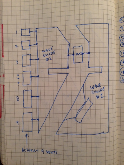
I always draw a diagram to show the elements, nodes, and interconnects before I code up the actual elements in Akabak. This is not needed for a simple 2 or 3 chamber box with a few vents. But for modeling the K15 or Karlsonator with a 9-element K aperture I definitely needed a schematic first.
Ok, right on, good old fashioned pencil and paper, I can do that
Right now I have one of the DCR scripts loaded up and i am goofing around with it just trying to get a feel for things ..
A Fluff Piece ...
Speaking of stuffing/filling/batting/lining or whatever you choose to call it: lowering the Q by adding fibrous material strategically located in the line (of certain types of cabinets) is considered good practice but also generally considered to be at least a little bit lossy .....right?
I just wonder if the real-world measured results sometimes show less loss than expected, or oddly enough even a GAIN somewhere in spectrum in some cases?!?!
Take a look at this graph that Brian Steele produced when stuffing and measuring his Tapped Pipe proof of concept, he actually shows a gain on the bottom end from stuffing!!! What do you guys make of this??? Is this just a fluke?
Attachments

Last edited:
- Status
- This old topic is closed. If you want to reopen this topic, contact a moderator using the "Report Post" button.
- Home
- Loudspeakers
- Subwoofers
- New sub design? Constricted Transflex, simple build (series tuned 6th order)