@Arch Stanton,
Oh, I am afraid your right! I can only use a grounded brass cilinder at the outside of the coil, as a housing... [Immidiately I opened my ball pen and measured the inner diameter of the plastic ink tube: 1,9 mm. That doesn't fit.]
So the material of the cylinder is a serious problem... Well, I can use a teflon tube for experiments. But that's not a solution for a serious cartridge. I will think about it. Thanks for the warning!
@Arch Stanton,
Each coil is isolated by some transparent plastic foil (all around the coil). The housing is a square tub (iron). I have opened other MM cartridges and the situation don't differ much.
Nevertheless, it is a problem. I have ordered some FEP tubes, but after all: is a tube between the coils and the magnet really necessary? The uppermost magnet is just fixed and only the rod under the moving magnet have to slide to and fro a cylinder.
So there are more solutions than only the choice of a cylinder made from the right material.
An externally hosted image should be here but it was not working when we last tested it.
Without a cylinder between the coils and the bottom magnet it will look a bit like the image above.
At the side of the bottom magnet there a 4 really small arrows. The point in the middle of these arrows - hardly visible - envelopes the movements of the tip of the stylus.
Last edited:
Fascinating stuff Tom (Henk)
This is way over my head, but the principles are understandable. However, I fail to see how you mechanically attach the canteliver, and I also do not quite get how the coupling, lower magnet - carbon rod - prism - stylus tip -, works. The stylus will mostly move in a side to side motion, but the resulting movements of the complete system, will have to be in a 45 degree angle to this. Thus the polycarbonate prism will act as a "grinder" on the carbon rod, correct?
Steen
@Dyolf,
Indeed, it is fascinating that there are still designs, that are not tested in the past. Although not everyone will try to make mini-scale objects like cartridges.
From that point of view I think that most people will prefer to DIY the tonearm, because this tonearm facilitates the cartridge very well. You can find the details at EXPLORING: VINYL AUDIO – DIY linear tonearm
Brassnwood has already made this tonearm (now he will try a 40 cm version) and ChrisG139 will make one too. I am curious about ChrisG139’s opinion.
@Dyolf,
Sorry, I forgot the second part of your post.
The cantilever is attached at the cartridge like a caravan behind a car: free to move in every direction. The stylus, prism and cantilever are rigid together.
A "grinder"... Well, call it a slider! ;-) I think that some silicon spray will be necessary.
The movements of the stylus of the cartridge have to be the same as the movements of the vinyl cutting machine (see http://phia.home.xs4all.nl/tsu/SC.avi)
@AVWERK,
May be your conclusion is too fast.
The mass of the stylus and the cantilever are negligible in relation to the mass of the cartridge and attached tonearm. Therefore, the importance of the relation of the mass of stylus and cantilever in comparison to the mass of the cartridge has another background. If you observe the design of the old hifi cartridges with the suspension half way the cantilever, you will see that they used quite massive cantilevers. Just because the mass is not so important when the suspension is attached nearby the stylus. And remind the swivelling wheel: correcting the direction of the wheel nearby the pivot needs a lot of force. But nearby the centre of the wheel it is quite easy.
The friction of the slider. The sliding movement of the rod against the prism is minimal. And is – of course – only a small % of the signal (vibrations of the magnet). The repulsive force keeps the rod against the prism so I don’t see the trouble. Moreover... the contact between the rod and the prism is like an not modulated groove. Have you ever outspoken your doubt about the use of un-modulated grooves?
I am missing something here?
The added mass that is connected to the cantilever - or is the cantilever NOT connected to that polycarbonate thing, connected to some magnets that move? - will be an excessive addition.
_-_-
PS. take a look at AT's method for moving magnets...
The added mass that is connected to the cantilever - or is the cantilever NOT connected to that polycarbonate thing, connected to some magnets that move? - will be an excessive addition.
_-_-
PS. take a look at AT's method for moving magnets...
The graph below is the result of experiment 1 with different weights upon the upper magnet. Horizontal the distance between both magnets and vertical the weight.
The movement of the magnet – caused by the stylus – is max 25 micron. The VTF will be something around 0,75 gram. So the movement of the magnet is a vertical line in the graph of 25 micron width at a distance of nearly 1,45 mm from the other magnet.
Conclusion: there is hardly any difference in the strength of the magnetic force in all the positions of the stylus in relation to the centerline of the groove.
An externally hosted image should be here but it was not working when we last tested it.
The movement of the magnet – caused by the stylus – is max 25 micron. The VTF will be something around 0,75 gram. So the movement of the magnet is a vertical line in the graph of 25 micron width at a distance of nearly 1,45 mm from the other magnet.
Conclusion: there is hardly any difference in the strength of the magnetic force in all the positions of the stylus in relation to the centerline of the groove.
Keep up the good work TomThe movement of the magnet – caused by the stylus – is max 25 micron.
")
25 micron - that is the width of the thinnest type of human hair. Is that really the maximum complete distance a stylus travels sideways in the groove?
Steen
In your design the repulsion between the magnets acts as a (non-linear) spring force in the kinematic system that includes the stylus-cantilever-polycarbonate prism-carbon rod-lower magnet mass. It would be instructive to calculate the resonant frequency of this "spring"-mass system to confirm that it lies comfortably outside of the audio band.
@Dyolf,
The image below shows the cross section of a cantilever (ID = 0,3 mm; OD = 0,5 mm). Inside the tube there is a cross section of the average groove. The width of the groove is not equal to the amplitude of the tip of the stylus. The figures at the right shows the 2 linear movements of the vinyl cutting machine and the surface area of the rotated square is the “real” position of the tip of the stylus: about 25 micron width.
The linear movement of 25 micron is too small to worry serious about the non-linearity of the repulsive forces between the 2 magnets in every cylinder. Nevertheless, the graph shows that the best VTF for one cylinder – in relation to the linearity of the frequencies between 40 – 20.000 Hz – is a weight nearby 0,75 gram or higher. Fortunately 2 x 0,75 gram is the average VTF for most cartridges. So I expect a nice flat graph when the cartridge is measured by a spectrum analyzer (with the right source). But friction between the prism and the rod can influence the generation of the electric signal.
@kevinahcc20,
When I was an expert in resonances, I should do this. But at the moment I don’t worry about it. It is much easier to build a proto type than to dive into all the theoretic about resonances, when I don’t know the finally material/mass of – for example – the rod.
There have to be a cause for a system to “slide” into resonance and my experience is that a proper mechanical design (the handling of all the forces) mostly will avoid self resonance. Therefore, the centerlines of both cylinders have to cross just at the tip of the stylus (visible in the drawing).
The image below shows the cross section of a cantilever (ID = 0,3 mm; OD = 0,5 mm). Inside the tube there is a cross section of the average groove. The width of the groove is not equal to the amplitude of the tip of the stylus. The figures at the right shows the 2 linear movements of the vinyl cutting machine and the surface area of the rotated square is the “real” position of the tip of the stylus: about 25 micron width.
An externally hosted image should be here but it was not working when we last tested it.
The linear movement of 25 micron is too small to worry serious about the non-linearity of the repulsive forces between the 2 magnets in every cylinder. Nevertheless, the graph shows that the best VTF for one cylinder – in relation to the linearity of the frequencies between 40 – 20.000 Hz – is a weight nearby 0,75 gram or higher. Fortunately 2 x 0,75 gram is the average VTF for most cartridges. So I expect a nice flat graph when the cartridge is measured by a spectrum analyzer (with the right source). But friction between the prism and the rod can influence the generation of the electric signal.
@kevinahcc20,
When I was an expert in resonances, I should do this. But at the moment I don’t worry about it. It is much easier to build a proto type than to dive into all the theoretic about resonances, when I don’t know the finally material/mass of – for example – the rod.
There have to be a cause for a system to “slide” into resonance and my experience is that a proper mechanical design (the handling of all the forces) mostly will avoid self resonance. Therefore, the centerlines of both cylinders have to cross just at the tip of the stylus (visible in the drawing).
@bear,
The magnetic repulsive force (mrf) in each cylinder can push maximal 60 gram. Along the 25 micron linear “trajectory” of the bottom magnet this mrf is nearly linear.
Therefore, the amplitude of the stylus – caused by the local modulation of the groove – will not be influenced by the added mass of the bottom magnets, the rods, the prism and even the mass of the stylus and cantilever.
As long as the mass of the VTF is far more than the mass of these moving parts, the mrf can “handle” the displacement of all the moving mass. The average VTF is about 1,5 gram so the mrf can even handle the inwards force to the centerline of the groove by the pull of the record (the cantilever acts as a rope that pulls the cartridge and tonearm).
Therefore, the stylus of this hypothetical cartridge will move freely "within" the groove.
Last edited:
Mk.2 Floater
Hi All,
Sorry to take you away from the cart. Discussion but ……
…. It seems ages since I started Floater Mk.2 but have finally got as far as testing it!
My Mk.1 was with a shortened c/weight ‘tail’ [#1] but Tom recommended the full arm length of 400mm [stylus to tail], so who am I to argue?
He was right tho’ as it gives more control over self-aligning the ‘90deg to centre line from spindle.’
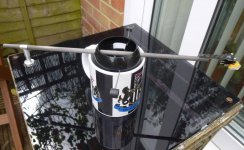
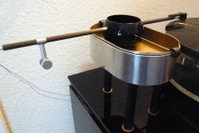
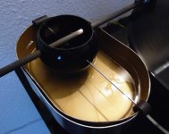
In the garage I found some leftover motorbike fuel hose which I cut into 2 x 20mm lengths, then sliced down one side & drilled a 2mm hole thro’ one face. Perfect for holding in place the horizontal bar, which can be adjusted easily on the fly.
Still using the ‘Ice Cream Tub’ but this time with a 1mm sheet of ally roughly formed to support it better & of course the old broom handle for the legs.
First tests were with my 35year old Linn K9 cart, warmer than my SAE1000 but, sounded great although obviously with less detail.
As Tom has said before ‘His Floater’ will bring out the best in ANY cart. You Guys gotta try it
No apologies for the pics, I am just a bad photographer!
Cheers,
GC
Ps. How you getting on with yours, chrisg?
Hi All,
Sorry to take you away from the cart. Discussion but
………. It seems ages since I started Floater Mk.2 but have finally got as far as testing it!
My Mk.1 was with a shortened c/weight ‘tail’ [#1] but Tom recommended the full arm length of 400mm [stylus to tail], so who am I to argue?
He was right tho’ as it gives more control over self-aligning the ‘90deg to centre line from spindle.’
In the garage I found some leftover motorbike fuel hose which I cut into 2 x 20mm lengths, then sliced down one side & drilled a 2mm hole thro’ one face. Perfect for holding in place the horizontal bar, which can be adjusted easily on the fly.
Still using the ‘Ice Cream Tub’ but this time with a 1mm sheet of ally roughly formed to support it better & of course the old broom handle for the legs.
First tests were with my 35year old Linn K9 cart, warmer than my SAE1000 but, sounded great although obviously with less detail.
As Tom has said before ‘His Floater’ will bring out the best in ANY cart. You Guys gotta try it
No apologies for the pics, I am just a bad photographer!
Cheers,
GC
Ps. How you getting on with yours, chrisg?
Attachments
- Status
- This old topic is closed. If you want to reopen this topic, contact a moderator using the "Report Post" button.
- Home
- Source & Line
- Analogue Source
- New principle linear tonearm and phono cartridge (DIY)