did you keep the two phases (4 wires) of the motor supplied with the cap to one of them (2 wires)?
Yes, I did. I only bypassed the 10k resistor in the thorens.
greetings, MArco
solved problem partly
Well,
I've solved the problem of the wowing turntable partly.
It proved that my gainclone amp which amplifies the signal of the sinus-generator was oscillating and losing a lot of power on that. Having that solved it seems that the amp has just enough power to drive the motor trough the step-up transformer.
What I want to do now is mto measure wow and flutter so that I can strive to the optimum.
So I've put a test record with sinus-signals on the turntable and recorded the signal with my soundcard on my harddisk.
Visisual inspection does not lead to a usable assesment of wow and flutter (it can't be seen). So some analysis on the signal has to take place. Does anyone have a clue how to do this. DOes anyone know (free) software wich can be usefull???
MArco
Wow and flutter is frequency modulation, so it gently changes the frequency of the replayed signal. If you were to multiply the replayed signal by a known constant frequency signal, you would get sum and difference frequencies. If you replayed 1kHz and multiplied it by 1kHz, then the sum would be 2kHz and the difference 0Hz. If you low-pass filtered, you would be left with 0Hz. However, wow and flutter will cause the 0Hz not to be 0Hz and that's how you measure your W&F. Dedicated audio test sets sometimes included W&F measurement. Bear in mind that if the test LP isn't concentric it will cause W&F.
Dear EC8010
thank you for your explanation. but...
Well, in the past I did some signal analysis on pressure levels underneath water waves. Then I performed a few tricks I dont understand nowadays. Apperently unlearning is as easy as learning. In short:
HELP I dont understand:
Multiplying 1khz with 1 khz gives me a sum of 2 khz and a difference of 0 Hz? How do I do this multiplication? The low-pass filtering I can get done.
thank you for your explanation. but...
Well, in the past I did some signal analysis on pressure levels underneath water waves. Then I performed a few tricks I dont understand nowadays. Apperently unlearning is as easy as learning. In short:
HELP
I dont understand:If you were to multiply the replayed signal by a known constant frequency signal, you would get sum and difference frequencies. If you replayed 1kHz and multiplied it by 1kHz, then the sum would be 2kHz and the difference 0Hz. If you low-pass filtered, you would be left with 0Hz.
Multiplying 1khz with 1 khz gives me a sum of 2 khz and a difference of 0 Hz? How do I do this multiplication? The low-pass filtering I can get done.
The sum and difference thing comes from the trigonometrical identities:
sin(A+B) = sinAcosB + cosAsinB
sin(A-B) = sinAcosB - cosAsinB
Adding the two identities gives:
sin(A+B) + sin(A-B) = sinAcosB
You recover sinA from the LP and multiply it by your local oscillator cosB, giving you sin(A+B) (sum frequency) and sin(A-B) (difference frequency).
(By the way, I'm not a smartarse - I had to look up the identities.)
You need a four-quadrant multiplier. Once upon a time, all broadcast vision equipment contained one from vision mixers to PAL coders. The ubiquitous part was the Motorola MC1496.
A quick search found:
http://www.analog.com/en/prod/0,,773_862_AD834,00.html
I'm afraid multipliers were always expensive. But you might be able to get a sample? Alternatively, it will probably be cheaper and easier in the long run to search ebay for a commercial W&F meter than building one from scratch.
I was originally going to post this on my turntable thread, but I think it would be of interest here.
I have been working on a design for a AC power supply that would have the following characteristics..
A) It needs to be stable
B) It needs to be clean
C) It needs to have a 2-phase output to eliminate the motor cap.
D) It needs to be easy to change the motor speed (frequency)
E) It needs to be easy to build
Getting 2 or 3 of the five requirements is pretty easy, but getting them all was proving to be frustrating until I came across the MAX 29X series of switched-capacitor low pass filters from Maxim. My thinking went in a new direction after that. These chips are a 8-Pole Low-Pass filter that turns a square wave into a low distortion sine wave. A .1% THD sine wave is what you get with no additional filtering, and it includes a uncommitted Op-Amp for an addition 2-Pole analog filter a cleaner sine. Or you can go hog-wild and cascade 2 of them for a –70dB Dist+Noise (the floor of the chip). All is not free however. In addition to the signal you want to filter, you need to provide a clock 100X the freq. you are filtering. It would seem a digital solution is in order. But wait…If you only need 1 frequency (and you know exactly what that is) no problem, but if you want multiple speeds and pitch control it gets a whole lot more complicated.
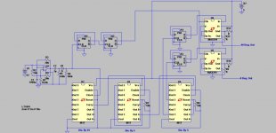
I’ve attached a schematic of my solution. It’s a analog/digital hybrid with analog on the ends and digital in the middle.
First the master clock. I’m using a simple op-amp oscillator with 2 timing components. The freq. is set by C1 and R1. Since all we need here is a pulse, you can use the crudiest op-amp you have on hand. This clock only needs to run 400X higher than the desired freq.. The values shown are for 24Khz, 400 times 60Hz. The stability of this oscillator is determined by the temperature coefficient of the timing components R1/C1. Mouser sells 30ppm/Deg. C ceramic caps for pennies, and a cheap metal film res. is around 20ppm. So without any temperature stabilizer your looking at a 50ppm Oscillator. Stabilizing the temp would be pretty easy with a LM34 based oven. The real bonus here is the ability to change speed by changing the value of R1.
The clock gets split into 2 paths. One goes to the cascaded D-FlipFlops (4013’s), A1 and A2. This sets up a “divide by four”, providing a clean 50% duty cycle signal at 100X freq. for the Max291’s clock. The other branch feeds to a bank of three 4017 decade counters. The first two form a “divide by fifty”. The 3rd one is the slick bit, it is setup as a “divide by four” divider, since the 0 thru 3 outputs sequences high, they are each high 25% of the time…in other words they are 90 deg. apart . Taking the count off of the 2 and 3 outputs gives me two signals with a 90 deg phase difference. These go to a flip-flop set up as a “divide by two” giving the signal its final division down to 60Hz, and turns the 25% duty cycle signal into a 50% duty cycle. This in turn is fed to the MAX 291 filters.
Not shown is the power section. It will be a chip amp driving step-ups. I also plan to implement some other features, but this should give you a good idea of how it works. Hopefully all the parts will get here in a week or so, so I can breadboard it.
If anybody sees something I’ve overlooked PLEASE let me know.
Casey
I have been working on a design for a AC power supply that would have the following characteristics..
A) It needs to be stable
B) It needs to be clean
C) It needs to have a 2-phase output to eliminate the motor cap.
D) It needs to be easy to change the motor speed (frequency)
E) It needs to be easy to build
Getting 2 or 3 of the five requirements is pretty easy, but getting them all was proving to be frustrating until I came across the MAX 29X series of switched-capacitor low pass filters from Maxim. My thinking went in a new direction after that. These chips are a 8-Pole Low-Pass filter that turns a square wave into a low distortion sine wave. A .1% THD sine wave is what you get with no additional filtering, and it includes a uncommitted Op-Amp for an addition 2-Pole analog filter a cleaner sine. Or you can go hog-wild and cascade 2 of them for a –70dB Dist+Noise (the floor of the chip). All is not free however. In addition to the signal you want to filter, you need to provide a clock 100X the freq. you are filtering. It would seem a digital solution is in order. But wait…If you only need 1 frequency (and you know exactly what that is) no problem, but if you want multiple speeds and pitch control it gets a whole lot more complicated.
I’ve attached a schematic of my solution. It’s a analog/digital hybrid with analog on the ends and digital in the middle.
First the master clock. I’m using a simple op-amp oscillator with 2 timing components. The freq. is set by C1 and R1. Since all we need here is a pulse, you can use the crudiest op-amp you have on hand. This clock only needs to run 400X higher than the desired freq.. The values shown are for 24Khz, 400 times 60Hz. The stability of this oscillator is determined by the temperature coefficient of the timing components R1/C1. Mouser sells 30ppm/Deg. C ceramic caps for pennies, and a cheap metal film res. is around 20ppm. So without any temperature stabilizer your looking at a 50ppm Oscillator. Stabilizing the temp would be pretty easy with a LM34 based oven. The real bonus here is the ability to change speed by changing the value of R1.
The clock gets split into 2 paths. One goes to the cascaded D-FlipFlops (4013’s), A1 and A2. This sets up a “divide by four”, providing a clean 50% duty cycle signal at 100X freq. for the Max291’s clock. The other branch feeds to a bank of three 4017 decade counters. The first two form a “divide by fifty”. The 3rd one is the slick bit, it is setup as a “divide by four” divider, since the 0 thru 3 outputs sequences high, they are each high 25% of the time…in other words they are 90 deg. apart
. Taking the count off of the 2 and 3 outputs gives me two signals with a 90 deg phase difference. These go to a flip-flop set up as a “divide by two” giving the signal its final division down to 60Hz, and turns the 25% duty cycle signal into a 50% duty cycle. This in turn is fed to the MAX 291 filters.Not shown is the power section. It will be a chip amp driving step-ups. I also plan to implement some other features, but this should give you a good idea of how it works. Hopefully all the parts will get here in a week or so, so I can breadboard it.
If anybody sees something I’ve overlooked PLEASE let me know.
Casey
Attachments
analysing the signal in the PC?
Yes, I understand that a hardware solution can be build or bought. But it should be possible to do all this in my computer once the signal from the LP is digitized. Or am I ??
??
Anybody any idea's. It shouldn't be that difficult. Even commercial software vendors have developed that.
Any freeware solutions avaiable? Or suggestions how such thing can be written?
You recover sinA from the LP and multiply it by your local oscillator cosB, giving you sin(A+B) (sum frequency) and sin(A-B) (difference frequency).
Yes, I understand that a hardware solution can be build or bought. But it should be possible to do all this in my computer once the signal from the LP is digitized. Or am I
??Anybody any idea's. It shouldn't be that difficult. Even commercial software vendors have developed that.
Any freeware solutions avaiable? Or suggestions how such thing can be written?
analysing with PC continued
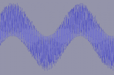
Well, Using AudacityAudacity its possible to do al kinds of programming via the Nyquist prompt. I succeeded in multiplying my digitized 2000Hz wave with a pure 2000Hz wave. The result: (see image).
Anybody knows how to proceed from here?
greetz, MArco
Yes, I understand that a hardware solution can be build or bought. But it should be possible to do all this in my computer once the signal from the LP is digitized. Or am I ??
Well, Using AudacityAudacity its possible to do al kinds of programming via the Nyquist prompt. I succeeded in multiplying my digitized 2000Hz wave with a pure 2000Hz wave. The result: (see image).
Anybody knows how to proceed from here?
greetz, MArco
Attachments
think before you post
I thought of it myself (Yes I know I should have thought before I posted
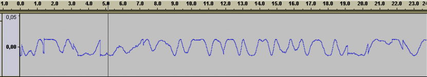
What I did: apply a low pass filter (100 hz) and voila, there is the wow and flutter signal.
So i continued by writing a Nyquist plug-in for Audacity to this automatically:
;nyquist plug-in
;version 1
;type process
;name "Wow and Flutter..."
;action "Distilling wow and flutter signal..."
;info "Frequency of the signal"
;control f "Frequency" real "Hz" 250 500 4000
(lp
(lowpass8
(mult s (hzosc f))
100)
110)
Name the above wow_and_flutter.ny, put it in the plug-ins folder and it works. Select a piece of recorded audio, select wow and flutter from the effect menu and the wow and flutter part of the signal is returned (see attached image).
This analysis is very dependent on having the frequency exactly right. So before doing this trick, determine the exact frequency of the recorded signal (still working to get that programmed as well). You can get a good estimate in the image spectrum menu of audacity.
Now starts the interpreting part
Well, Using AudacityAudacity its possible to do al kinds of programming via the Nyquist prompt. I succeeded in multiplying my digitized 2000Hz wave with a pure 2000Hz wave. The result: (see image).
Anybody knows how to proceed from here?
I thought of it myself (Yes I know I should have thought before I posted
What I did: apply a low pass filter (100 hz) and voila, there is the wow and flutter signal.
So i continued by writing a Nyquist plug-in for Audacity to this automatically:
;nyquist plug-in
;version 1
;type process
;name "Wow and Flutter..."
;action "Distilling wow and flutter signal..."
;info "Frequency of the signal"
;control f "Frequency" real "Hz" 250 500 4000
(lp
(lowpass8
(mult s (hzosc f))
100)
110)
Name the above wow_and_flutter.ny, put it in the plug-ins folder and it works. Select a piece of recorded audio, select wow and flutter from the effect menu and the wow and flutter part of the signal is returned (see attached image).
This analysis is very dependent on having the frequency exactly right. So before doing this trick, determine the exact frequency of the recorded signal (still working to get that programmed as well). You can get a good estimate in the image spectrum menu of audacity.
Now starts the interpreting part
Attachments
Continuing
Well, I've been busy building all sorts of things (amps, turntable, arm, kitchen), but I got around to this again.
Earlier I mentioned I had a lot of wow and flutter using the PS. That was due to a cold joint. The mass (earth) of the oscillator was not joined to the mass of the amp. Having fixed that things improved. Result definately better than mains .
In my new turntable (look for posts in a few days), I can't change speed to 45 rpm by running the belt over a larger pully, so I decided that I want to have a second frequency generated, for higher speed.
I've worked out the right frequency, and build an oscilator for that. Altough the sine was lookuing good it dind't work. The motor just vibrated and didn't run. I suspect the phase shifting cap. I think it should have a different value for a different frequency. Does anyone know how to calculate this value?
thanx, MArco
By the way. I never figured out how to extract the frequency of the recorded sound I mentioned earlier:
Cooledit can find it out automatically.
Well, I've been busy building all sorts of things (amps, turntable, arm, kitchen), but I got around to this again.
Earlier I mentioned I had a lot of wow and flutter using the PS. That was due to a cold joint. The mass (earth) of the oscillator was not joined to the mass of the amp. Having fixed that things improved. Result definately better than mains
.In my new turntable (look for posts in a few days), I can't change speed to 45 rpm by running the belt over a larger pully, so I decided that I want to have a second frequency generated, for higher speed.
I've worked out the right frequency, and build an oscilator for that. Altough the sine was lookuing good it dind't work. The motor just vibrated and didn't run. I suspect the phase shifting cap. I think it should have a different value for a different frequency. Does anyone know how to calculate this value?
thanx, MArco
By the way. I never figured out how to extract the frequency of the recorded sound I mentioned earlier:
This analysis is very dependent on having the frequency exactly right. So before doing this trick, determine the exact frequency of the recorded signal (still working to get that programmed as well). You can get a good estimate in the image spectrum menu of audacity.
Cooledit can find it out automatically.
Re: Continuing
The phase shift cap and the motor form a second order low pass filter, the phase shift of which will be 90 degrees at f = 1/2piSQRT(LC) where L is the motor coil inductance.
deduikertjes said:I think it should have a different value for a different frequency. Does anyone know how to calculate this value?
thanx, MArco
The phase shift cap and the motor form a second order low pass filter, the phase shift of which will be 90 degrees at f = 1/2piSQRT(LC) where L is the motor coil inductance.
Calc results
It runs on 33 rpm at 50 hz with a 0.15 uF cap.
So I need 45/33 *50 = 67.5 Hz for 45 rpm
Feeding that to the formula twice (once for determining the inductance, once for determining the capacity) gives me a Capacity of about 8.2 nF.
Will see if that works.
greetz, MArco
Thank you, that was what I was looking for. For the lazy ones my calculations for a typical old Thorens (TD160 motor):90 degrees at f = 1/2piSQRT(LC) where L is the motor coil inductance.
It runs on 33 rpm at 50 hz with a 0.15 uF cap.
So I need 45/33 *50 = 67.5 Hz for 45 rpm
Feeding that to the formula twice (once for determining the inductance, once for determining the capacity) gives me a Capacity of about 8.2 nF.
Will see if that works.
greetz, MArco
Hi,
from 150nF (=0.15uF) down to just 8.2nF for a small change in frequency does not sound right.
Use the first pass through the equation to determine the L value of the motor.
Then keeping the L value the same insert the higher frequency.
However, I would expect the error in phase to be of little significance between 50Hz and 67.5Hz. Could the cap be just a little too big for the higher frequency and prevent starting?
Try 120nF or 100nF, 8.2nF must be too low.
Re: Calc results
It's 82nF, I suspect a typo.
If you manipulate the formula you'll see that F2/F1 = SQRT(C1/C2) so for F2/F1 = 1.35, C1/C2 must equal 1.822.
150 / 1.822 = 82.3.
82 is as close as you'll get (don't forget caps are usually 10% tolerance)
deduikertjes said:
Feeding that to the formula twice ... gives me a Capacity of about 8.2 nF.
greetz, MArco
AndrewT said:Hi,
from 150nF (=0.15uF) down to just 8.2nF for a small change in frequency does not sound right.
It's 82nF, I suspect a typo.
If you manipulate the formula you'll see that F2/F1 = SQRT(C1/C2) so for F2/F1 = 1.35, C1/C2 must equal 1.822.
150 / 1.822 = 82.3.
82 is as close as you'll get (don't forget caps are usually 10% tolerance)
I was wondering about how well the calculation fitted the usual range of cap values when I realised that this leads to an easy approximation.
1.35 is approximately the 8th root of 10 so 1.35^2 is approximately the 4th root of 10, which makes it equal to the cube of the 12th root. Confused yet? Here's the rule:
The ratio of the caps between 33 and 45 will be three steps down on the E12 values.
If you start with say 100 then you step back three to 56, that's the new cap value.
Works for 78 too, but not as well. 2.36 is close to the 3/8th power of 10 so 2.36^2 is nearly the 3/4 power of 10 so it must also be the 9th power of the 12th root of 10. New rule:
The ratio between caps for 33 and 78 is 9 steps back (or three steps forward and drop a decade).
If you start with 100 you step forward three to 180 and then drop a decade to 18. The approximation is well within the 10% tolerance of the caps.
For those who aren't familiar with them, the E12 values are 1.0, 1.2, 1.5, 1.8, 2.2, 2.7, 3.3, 3.9. 4.7, 5.6, 6.8, 8.2, 10. The ratio for each step is approximately the 12th root of 10, hence the name E12.
Typo indeed
Excuse me. It was a typo indeed.
I knew it was not a good idea to present the result of my calculations.
But then it leads to a mind boggling but very useful post about cap values and rpm ratios. Sometimes from something bad comes something good.
Thank you, MArco
It's 82nF, I suspect a typo.
Excuse me. It was a typo indeed.
I knew it was not a good idea to present the result of my calculations.
But then it leads to a mind boggling but very useful post about cap values and rpm ratios. Sometimes from something bad comes something good.
Thank you, MArco
wien bridge oscillator behaving bad
Well, I'm not being lucky.
My TT PS runs on a classic wien bridge oscillator with a lamp as stabilizing element.
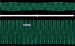
Frequency is very stable, but the amplitude is varying (too much to my taste; after the step-up transformer I've a variation of about 2,5 Volts on 90 Volts on average).
As I've included a variable resistor to set the oscillation I've played around with it. In theory the wien bridge shows least distortion when it just oscillates. It might do, but it shows the biggest amplitude variations. When I crank it up to a larger amplitude just before the waveform starts to show distortion the amplitude variations are smallest (but still to big).
(I've included a few screen shots of the recorded waveform)
Does anyone know how to have this oscillator behave a little better
?
Again any help greatly appreciated.
MArco
Well, I'm not being lucky.
My TT PS runs on a classic wien bridge oscillator with a lamp as stabilizing element.
Frequency is very stable, but the amplitude is varying (too much to my taste; after the step-up transformer I've a variation of about 2,5 Volts on 90 Volts on average).
As I've included a variable resistor to set the oscillation I've played around with it. In theory the wien bridge shows least distortion when it just oscillates. It might do, but it shows the biggest amplitude variations. When I crank it up to a larger amplitude just before the waveform starts to show distortion the amplitude variations are smallest (but still to big).
(I've included a few screen shots of the recorded waveform)
Does anyone know how to have this oscillator behave a little better
?
Again any help greatly appreciated.
MArco
Attachments
Your problem is that Wien bridges only work well when the thermal time constant of the thermistor (or lightbulb) in the amplitude stabilization network is considerably longer than the period of the wanted oscillation. When it isn't, it starts trying to control the oscillation causing the effects you've seen. There are various ways of making Wien bridge oscillators work at low frequencies. The easiest is to follow the oscillator with a precision rectifier, then smooth it with a very long time constant (a few seconds) and apply that DC to a FET to use the FET as a variable resistor in the amplitude stabilization circuit. This generally means that you need four op-amps instead of one. An even more complex method exchanges the FET for a four-quadrant multiplier...
- Status
- This old topic is closed. If you want to reopen this topic, contact a moderator using the "Report Post" button.
- Home
- Source & Line
- Analogue Source
- New power supply