As EC8010 said, your problem is the loop control.
If you do go for the rectifier approach, here are a few things that I have found improve the performance:
Use an LED / LDR pair instead of the lamp - the rectifier drives the LED, the LDR is the variable resistance. Perkin Elmer make a part called "Vactrol" which is a matched LED / LDR pair in a lightproof envelope. Get the low Tempco version (VTL5C1 I think.).
Use an elliptical filter rather than a standard one. The easiest way to describe the filter desired is that it's a high pass filter followed by a differential amplifier which amplifies the DC difference and rejects the AC common mode. If the diff amp is made variable you can tune it to achieve almost perfect rejection of one frequency (the ripple frequency).
By the time you've done all this you might as well junk the Wien bridge and use a modified Fraser phase shift oscillator to give you a quadrature tracking generator. The Fraser works by placing two all pass filters in series and then inverting the output of the last into the input of the first. The loop has 360 degree of phase shift at the 90 degree phase shift point of the all pass ilters.
Since the phase shift of the all pas is controlled by a single RC pair you can make the RCs variable with a double gang pot and match the caps and the thing will track with 90 degrees between the two intermediate outputs over the range of the RC adjustment.
Ouch!
Mark, EC8010 thank you, but your answers swept me off my feet a bit.
I hoped for something more simple.
If I'm not mistaken, my set-up used to perform much better (variations after the step up transformer only a few tens of a Volt).
When I heard a sort of wow in my turntable that I was not used to I started measuring. Then I saw the larger variations.
Could the cause also be that the lamp has deteriorated over time, or something stupid like that?
(or do I have better measurement apparatus nowadays so that I see variations that were not there before).
After all it should be possible to use a wien bridge to generate a sinus with enough precision to drive a turntable. Or shouldn't it?
greetings, MArco
I used to use a Wien bridge in my first ever TT drive and it worked reasonably well. Maybe I used a lamp with more thermal lag than yours. One thing which I know helped is to use two op amps in the Wien bridge with the AGC (the lamp) between them. The design I used is here:
Note the low impedance around the lamp
Further info at
http://www.members.iinet.net.au/~quiddity/audio/TTPS.html
Just one thing - when the Wien bridge is not driving the TT output amplifier, how does it perform?.
An externally hosted image should be here but it was not working when we last tested it.
Note the low impedance around the lamp
Further info at
http://www.members.iinet.net.au/~quiddity/audio/TTPS.html
Just one thing - when the Wien bridge is not driving the TT output amplifier, how does it perform?.
Re: Ouch!
Sadly, the answer is no. It is possible to add fixes to the Wien bridge to persuade it to work well at 50Hz, but by the time you've done that you could have built a more suitable oscillator. Like Mark, I favour quadrature oscillators.
deduikertjes said:After all it should be possible to use a Wien bridge to generate a sinus with enough precision to drive a turntable. Or shouldn't it?
Sadly, the answer is no. It is possible to add fixes to the Wien bridge to persuade it to work well at 50Hz, but by the time you've done that you could have built a more suitable oscillator. Like Mark, I favour quadrature oscillators.
Divided down crystal oscillators are obviously more accurate in terms of absolute frequency than any analogue oscillator. The thing is, you often don't need that accuracy. Turntable drive mechanisms (belt, idler) have a little slip and the slip varies with temperature, humidity, belt tension or idler pressure, so you usually need a fine tweak of frequency to get the speed exactly right. It is possible to vary the division ratio of the divider in a crystal oscillator (usually by changing the preload to a counter), but making the changes sufficiently small as to be almost unnoticeable (and usable) is quite hard, so a divided down crystal oscillator with a nice fine speed control is usually quite complex. I expect the best way to do it would be to program a PIC, but I'm not so hot on programming.
Edit: And the other problem is filtering that square wave down to a sine wave without the amplitude changing as you change frequency.
Edit: And the other problem is filtering that square wave down to a sine wave without the amplitude changing as you change frequency.
That's what I mean about precision.EC8010 said:.........Edit: And the other problem is filtering that square wave down to a sine wave without the amplitude changing as you change frequency.
What if there is a little/lot of distortion in the sinewave signal to the poweramp/motor?
AndrewT said:What if there is a little/lot of distortion in the sine wave signal to the poweramp/motor?
The motor doesn't like it and vibrates more than necessary. I know Mark prefers less distortion but I'm happy if it's below 1%.
Having read all the opinions and followed the interesting link of Mark I decided to try and tweak my wien bridge with another lamp.
If I want to choose such a lamp I guess I've to choose one which is designed to run at a higher voltage. Or ain't it that simple?
If tweaking doesn't work I think I'll use a cheap MP3 player. After all these come for less than 10 euro's nowadays. That seems to be the cheapest and easiest way to get a good 50 Hz sine (though it's not that much fun as building a thing myself).
greetings, MArco
I used to use a Wien bridge in my first ever TT drive and it worked reasonably well. Maybe I used a lamp with more thermal lag than yours.
If I want to choose such a lamp I guess I've to choose one which is designed to run at a higher voltage. Or ain't it that simple?
If tweaking doesn't work I think I'll use a cheap MP3 player. After all these come for less than 10 euro's nowadays. That seems to be the cheapest and easiest way to get a good 50 Hz sine (though it's not that much fun as building a thing myself).
greetings, MArco
AndrewT said:
That's what I mean about precision.
What if there is a little/lot of distortion in the sinewave signal to the poweramp/motor?
I will shortly be in a position to report exactly how important this is.
A bit of background: I recently designed a drive which is basically a digitally clocked DAC with variable clock frequency. To keep things very simple my DAC has only five levels - +1, x, 0, -x and -1. The level of third harmonic is entirely dependent on x. When x = 1/SQRT2 the third harmonic is suppressed (better than -70dB and ) for all other numbers it rises but in different phase according to whether x is greater or lesser than 0.707. Since the lowest harmonic otherwise produced is the seventh it is very easy to filter this to give good purity with variable 3HD levels.
I received the boards from the fab house today and found that they had made the wrong ones so it will be a week before I get to test the result. I think that if the motor has constant reluctance then zero 3HD is ideal. With a salient pole motor there might be some small effect counteracting the cogging due to salience which is what I want to test.
The octal counter that clocks the wave is duplicated with a 2 bit shift, creating a quadrature pair. BTW the clock divisions are around 1 part in 5000 so the output frequency steps are around 0.01 Hz at 50 Hz. The drive also has variable phase angle, master level control plus automatically switched levels for different drive frequencies and a timed "start up boost".
Re: Re: Ouch!
Hi EC8010,
Any possibility you could share your quadrature oscillator design? I'd be very interested in seeing it, as I imagine others here would be. Sounds like a great solution for a table with a low voltage synchronous motor like my TD125..
EC8010 said:
Sadly, the answer is no. It is possible to add fixes to the Wien bridge to persuade it to work well at 50Hz, but by the time you've done that you could have built a more suitable oscillator. Like Mark, I favour quadrature oscillators.
Hi EC8010,
Any possibility you could share your quadrature oscillator design? I'd be very interested in seeing it, as I imagine others here would be. Sounds like a great solution for a table with a low voltage synchronous motor like my TD125..
Re: Re: Re: Ouch!
You have mail. Or you would have if you allowed mail. I'll temporarily allow mail to me.....
kevinkr said:Any possibility you could share your quadrature oscillator design? I'd be very interested in seeing it, as I imagine others here would be.
You have mail. Or you would have if you allowed mail. I'll temporarily allow mail to me.....
I'm back
Sorry for resurrecting this thread, but as I started it I hope you don't mind I put my news here.
Well, the signal generator is finished. It's as follows:
- a PIC at 20MHz is doing the job of generating two signals
- It's done by means of PWM and a 200 points sine lookuptable
- Frequency is fully adjustable
- Phase shift also!
- Amplitude control is done by means of a digital potentiomenter and a poti in the ADC of the PIC
- There is a second order filter at the output.
I'm now in the poweramp stage!
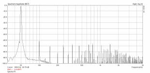
This is the spectra of the signal. Is by no means calibrated, and there could be some noise riding through. It's generated by PWM, and adjustable so far with 0.1Hz steps. The phase trimming is in 1,8º steps. A bit crude, but some improvements working with the firmware are certainly possible. Amplitude is controlled in 256 steps, with a digital potentiometer.
Attachments
- Status
- This old topic is closed. If you want to reopen this topic, contact a moderator using the "Report Post" button.
- Home
- Source & Line
- Analogue Source
- New power supply