Will these be huge changes compared to the first boards Wayne sold. Will your build be based on the new board.
Yes, of course it will be on the new PCB. I'll have an official guide with new photography.
Will these be huge changes compared to the first boards Wayne sold. Will your build be based on the new board. Still populating mine one resistor at a time unless the wife says otherwise.
The only thing added is the resistance in series with the pot and all boards had that the very first schematic didn’t.
Same for me please. Oh and the dimensions of the PCB so I can spend ages finding the right case and knobs.... [emoji16][emoji16]Is the a BOM available, I'd like to start picking up parts as soon as possible so when the boards are ready so will I.")
Update - The final configuration should be posted soon. The current PCB is fine, there will be a few tweaks to the schematic.
Documentation will contain the BOM.
The ball is rolling on getting the PCB into the diyAudio store, but this is never a fast process.
The best bit of news is the one I made with jellybean parts is fantastic sounding! Using a $0.50 ON Semi LM833 opamp and IRF 610/9610 outputs.
Documentation will contain the BOM.
The ball is rolling on getting the PCB into the diyAudio store, but this is never a fast process.
The best bit of news is the one I made with jellybean parts is fantastic sounding! Using a $0.50 ON Semi LM833 opamp and IRF 610/9610 outputs.

Thanks!
To Wayne, 6L6, and diyaudio! I look forward to building this when the final boards, BOM are available.
Looks like a donation to DIYaudio is also in order.
Yes, I agree.
This was always going to be a project suitable for a wide range of builders, and having a solid PCB and configuration to ensure success has been important. I think we've finally gotten there.
To Wayne, 6L6, and diyaudio! I look forward to building this when the final boards, BOM are available.
Looks like a donation to DIYaudio is also in order.
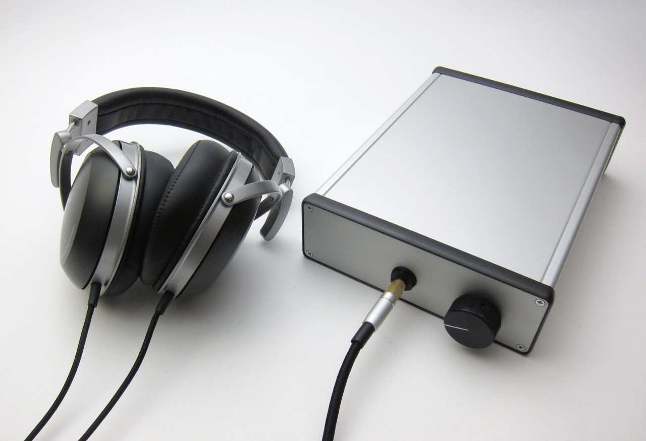
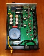
This is the new board with a build using no exotic parts. It sounds absolutely wonderful! (In this example my favorite has been a $0.50 OnSemi LM833 and IRF610/9610 output mosfet.)
The official guide is in-progress. PCB will be in the diyAudio store in the not-distant future.


The official guide is in-progress. PCB will be in the diyAudio store in the not-distant future.
Attachments
> It sounds absolutely wonderful!
So no need to spend USD 3500 for a Pass Labs HPA1 ?
Cheers,
Patrick
Please compare ;-)
Google-Ergebnis fur https://www.stereophile.com/images/616passlabs.inside.jpg
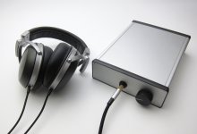
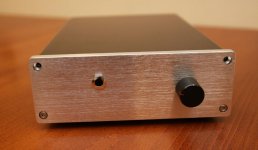
A build of mine. No CNC finish on the case yet, maybe later ...
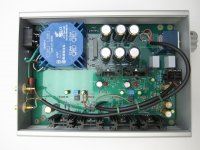
The most dificult were the the output transistors 2SK2013/2SJ313 - matched quad (2N,2P) was bought form liubincalvin forum user.
Plays nicely, however, the default gain setting is a bit low my taste (Senheisers HD600 needs more)
The most dificult were the the output transistors 2SK2013/2SJ313 - matched quad (2N,2P) was bought form liubincalvin forum user.
Plays nicely, however, the default gain setting is a bit low my taste (Senheisers HD600 needs more)
Attachments
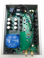
and , worst thing is that you don't need any matching with this circuit
Yes, I agree, optocoulpler bias regulation works like a charm.
Nevertheless, 2SK2013/2SJ313 available on the market are just fakes. You better use FQP3N30 / FQP3P20 instead ... or just buy from a trusted source, were matched transistors are also available
This is the new board with a build using no exotic parts. It sounds absolutely wonderful!
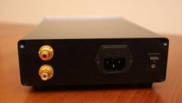
Jim, I don't know whether this is the right place to ask - how did you cut the rectangular hole in aluminum for power entry module?
Thank you!
- Status
- This old topic is closed. If you want to reopen this topic, contact a moderator using the "Report Post" button.
- Home
- Amplifiers
- Pass Labs
- New PassDIY Headphone Amp (now available)