XP-10 / Specifications
Overall Gain
-73 dB to +10 dB
Volume Steps
83
Input Impedance
96k bal, 48k single-ended
Output Impedance
1000 Ohm bal, 150 Ohm single-ended
Using SE outs
Input is vinyl with XONO
Gain 40dB
Max Output 20V RMS
Output impedance 300 ohms
Gain of this headphone amp - 6L6 or Meldano please help
2 pico - I have tried other op amps with same results - will look at surrounding components - quite possible I put the same incorrect component in both channels given my board stuffing habits
Thanks
Bob
pico
I just completed my M2 so I substituted it in the chain - works well
Checked input rca connectors and 4 pin XLR - no shorts
DC offset left channel is is 175mV and right channel is 50mV - I expected better.
Anyone who has built this have measurements?
I have tried other op amps with same results.
Will start checking all resistors.
Thanks and best
175mV seems quite high for a headphone amp. I'd personsally want below 10mV.
Totally agree
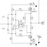
Are you using 2sk2013/2sj313 on output?
Yes
Did you use these output stage:
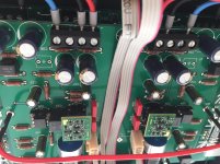
I found out that the R6, R15, R23 an R24 which are all 10K, must be real close, to have an almost zero output offset. Especially R6 and R24 if I remember correctly.
Also the V+ and V- of the PSU must be real close and stable.
Variations between v+ and V- give offset.
When I measured a few 10K resistors and picked the closest together, I now have output offset around 0.8 - 1mV at both channels.
Attachments
You can fix dc offset by changing R6 to 9.8k and add 500 Ohm trimpot.
That doesn't help you fix the main issue though.
thanks pico - nice solution to that problem
The project is not dead, due to life outside this forum I kicked the can down the road quite a bit further than I intended... Any delay (I.E., the last 6-7mo or so...) is 100% mine.
I saw your comment and realized that it was languishing on my shelf, dusted it off and started messing with it again over the last 2 days.
Long story short, and not trying to offer any excuses for my dropping of the ball with this project, I think I've finally found a configuration that is bulletproof and sounds great.
So hang in there, if it all works I'll have a substantive update soon.
Any updates?
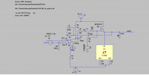
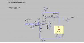
Well since I am waiting for boards for this amp and also only have a few 2sk2013 and no 2sj313, I removed about half of the passdiy headphone circuit and made it work with the one transistor. Well at least it works in simulation. I wonder if it will work in the real world?
Attachments
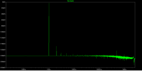
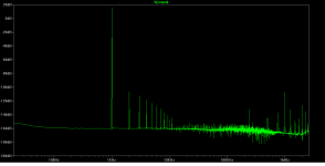
I've been using ltspce for only a very short time now so I don't know it very well but I will take a guess that the FFT analysis for this circuit is pretty optimistic. The Passdiy amp looks even more optimistic. I assume that accurate FFT circuit simulation can't be done. If not I'll just have to wait and measure the passdiy board with the Arta program, I'm sure it will show a more realistic
picture.
picture.
Attachments
Last edited:
")
And what did you think?
In my setup (AKG K812) the OPA627 is the better one.
- Status
- This old topic is closed. If you want to reopen this topic, contact a moderator using the "Report Post" button.
- Home
- Amplifiers
- Pass Labs
- New PassDIY Headphone Amp (now available)