Enhancing the performance of this CCS - which is exposed to everything incoming on the line - is definitely worth experimentation for the Jung superreg, and I can confirm it makes a worthwhile improvement in PSRR for the ALWSR boards. Audible performance, too. I've done this for years, for the price of one extra resistor and cap (nothing fancy required, just a smallish electrolytic)Possibly a worthwhile tweak is do what Doug Self does with his CCS in his power amps and split R into 2 for the main led CCS (that drives the output follower) in these designs and add a capacitor at the midpoint.
Jan, I suspect this was an intentional act rather than a mistake, but capacitor C7 from the original TAA Part3 article, is omitted from your PCB and your schematic. I imagined there might have been discussion about C7 on this thread, and indeed I did search for "C7" but found nothing.
Schematic snippets below for comparison.
-Mark
Mark, good catch - it is indeed my error.
I will correct the files and PCB.
jan
From what I can see, this "new" PCB design is simply the vintage 1995 design, with the op amp rails bootstrapped. No pre-reg (vintage 2000). No shunt opn (vintage 2012 WJ aX interview).
It is a good thing to have the PCBs available for the older design, for sure. But it is also a missed opportunity to not upgrade with other worthy improvements. They might be an option.
Is the Andy Weekes PCB actually available? I clicked on the suggested link and got an error.
Hi Walt, thanks for chiming in.
Indeed, as I mentioned in the web post, it is simply the PCB from the initial series, with the opamp supply bootstrapped per your 4/2000 article.
I did not have the ambition to embark on another potentially long-term project, especially not after Jack Walton's tests showing that this supply is at the very top of the list, performance-wise.
It is simply as a service to those people that have in the past contacted me about availability of those OCSL PCBs.
jan
Enhancing the performance of this CCS - which is exposed to everything incoming on the line - is definitely worth experimentation for the Jung superreg, and I can confirm it makes a worthwhile improvement in PSRR for the ALWSR boards. Audible performance, too. I've done this for years, for the price of one extra resistor and cap (nothing fancy required, just a smallish electrolytic)
Agreed and it causes no loss of headroom unlike the bootstrapped J310 I was suggesting. Both Self and WJ in his articles in particular, has measured this approaching the noise floor of the AP system and perform well upto hundred of Khz's. The impression I got is that some people never liked the sound with the floating pre-reg - a bottleneck?. Spec's are a different issue.
Last edited:
Peranders,
Can your reg be adjusted slightly to allow for 36V output? I would like to have it for personal comparison with Jung/Didden reg in phono stage?
You can have higher output voltage than the opamp can take since I have room for a zener for the supply of the opamp. I have never tested this function though.
Jan, I suspect this was an intentional act rather than a mistake, but capacitor C7 from the original TAA Part3 article, is omitted from your PCB and your schematic. I imagined there might have been discussion about C7 on this thread, and indeed I did search for "C7" but found nothing.
Schematic snippets below for comparison.
-Mark
I'm pretty sure that C7 is needed.
An externally hosted image should be here but it was not working when we last tested it.
Peranders,
Can your reg be adjusted slightly to allow for 36V output? I would like to have it for personal comparison with Jung/Didden reg in phono stage?
You can try the OPA604 as the error amplifier, Vs max is 48V. (I haven't tested this for PSRR, Noise and Z-out.)
Mine arrived two days ago. It looks great (you got major compliments from a very picky graphic designer/artist type) and feels expensive. An excellent mix of theory (e.g., Touzelet), practical tips (e.g., Simon), and incredibly useful construction projects (e.g., Cordell). And none of the wince-worthy stuff that I have to wade through in other publications to get to the useful nuggets.
Speaking of Pierre, Jan, could you convince him to update "Simple Approximations of Tube Anode Characteristics" for LA and post the XLS sheets using "MS-Solver" on the LA website? I am not as good with "the Euclidian positive norm" as I am with a soldering pencil.
Spent some time studying "Solver":
DIY Test Equipment for Audio and Ham Radio Enthusiasts
An externally hosted image should be here but it was not working when we last tested it.
DIY Test Equipment for Audio and Ham Radio Enthusiasts
> With your permission, can i redesign it using SMD?
I am 10 days too late in replying (was not watching), but 6 months earlier with the SMD design.
(Jan knew about this since day 1.)
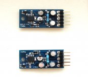
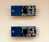
These first prototypes are now fully tested, and will be given to Jan Didden tomorrow.")
There is also a simpler version (designed but not yet tested).
Same size PCB (14.5x36mm), using TO220 sized pass devices.
SO no soldering of the pass device onto PCB required (not for beginners).
Patrick
I am 10 days too late in replying (was not watching), but 6 months earlier with the SMD design.
(Jan knew about this since day 1.)
These first prototypes are now fully tested, and will be given to Jan Didden tomorrow.
There is also a simpler version (designed but not yet tested).
Same size PCB (14.5x36mm), using TO220 sized pass devices.
SO no soldering of the pass device onto PCB required (not for beginners).
Patrick
Attachments
I should add that I took the liberty to change a few things to suit my own use.
So it is not identical to the published version from Walt and Jan.
Hope they wouldn't mind.
Amongst others :
Voltage reference and zener are replaced by Panasonic SMD LEDs (3 in series)
Higher resistor and lower capacitor values for RC filters (to allow this size)
JFET input opamp (15V version uses OPA1641).
2x 2SK209BL degenerated to 3mA as current source for V_ref and start-up bias
Pin-out's are 78xx / 79xx compatible, with (optional) additional pins for output and ground sense.
Patrick
I don't mind you soon the work. I am sure yours would be better option, regardless. Thank you for providing it. I may still may do a higher voltage version using opamp Jack suggested. Been looking at other options, but nothing jumps out. Really want to try it on a rIAA stage.
. I am sure yours would be better option, regardless. Thank you for providing it. I may still may do a higher voltage version using opamp Jack suggested. Been looking at other options, but nothing jumps out. Really want to try it on a rIAA stage.We did it for ourselves, for fun, for the challenge. And I posted just now only to show you how we did it.
It was not too easy to fit everything in this footprint, and still have a large (unstuffed) pad at the back for heat sinking.
We have no plans to sell them if that was what you were suggesting.
It is not our intellectual property.
I did promise Jan an article for Linear Audio Vol. 7 on these though.
Maybe he'll give away free PCBs with the book ?
Patrick
- Home
- General Interest
- Everything Else
- New Linear Audio publication!