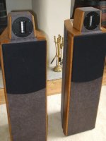
I thought I'd share details here of my latest loudspeaker project.
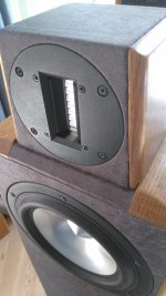
Jordan JX150NG
Aurum Cantus G2si
2nd order H.P.
3rd order L.P.
Crossover 3.5kHz
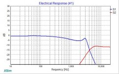
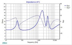
The passive crossover was designed using frequency response, impedance and phase measurements of the drive units in the
enclosure. Phase tracking through the crossover region is as close as I could get it whilst keeping the high pass section 2nd order to avoid the need for a second capacitor. The jx150ng response starts to wiggle above 2.5kHz which didn't help so I aimed for close phase tracking through, and either side of the crossover rather than a deep reverse null. I Later fine tuned the inductor and resistor values to account for actual measured capacitor values. The high pass capacitor is teflon film/foil.
The metal grill has been removed from the ribbon for improved transparency, my thanks to mikelm for this suggestion as it makes a remarkable improvement. The treble enclosure sits on the main enclosure via a concealed fixing which both holds the unit in place and allows some forward/backward movement for fine tuning of phase via adjustment of the vertical offset should it be necessary. At present the offset is set for best overall phase tracking following my simulations and I haven't felt any need to alter this but according to simulation forward adjustment of 1/4" from its current position should offer a deep reverse null should I decide to see which actually sounds better.
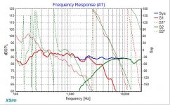
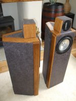
The crossover is situated in a separate compartment in the base of the main enclosure which is 3/4" ply with a ceramic lining and cross bracing for rigidity. At 25L (sealed) it is on the small side for the JX150NG but at 25kG it is already heavy so rather than accommodate the reduced size by lowering the Qts of the Jordan via a resistor across its second voice coil which would have reduced efficiency, the response was equalized to remove the resultant slight bass lift of 1dB or so via a resizing of the input capacitor on the amplifier input, preserving efficiency and reducing the amplifier's work load. The resulting bass roll off integrates well with a subwoofer, in this case at 65Hz.
Subjectively there is a lovely sense of precision plus resolution. Depth and width spacial information is excellent and the treble is extremely light and airy. It has incredible ambience and is a real joy. Instruments and voice are at least as focused as my trusty Quad ESL63s, and in some ways actually better. Despite the less than ideal Jordan roll-off the midrange is really good too with clean detail and plenty of it without any noticeable transition to the treble...to my relief.
Possible future improvements?
1. Maybe swap the laminated steel bass inductors for air core. These are 0.9mH and 0.56mH. Suggestions here would be very welcome.
2. Possibly replace the MOX resistors in the treble section with something else?
Thoughts/suggestions welcome.
Tim
Jordan JX150NG
Aurum Cantus G2si
2nd order H.P.
3rd order L.P.
Crossover 3.5kHz
The passive crossover was designed using frequency response, impedance and phase measurements of the drive units in the
enclosure. Phase tracking through the crossover region is as close as I could get it whilst keeping the high pass section 2nd order to avoid the need for a second capacitor. The jx150ng response starts to wiggle above 2.5kHz which didn't help so I aimed for close phase tracking through, and either side of the crossover rather than a deep reverse null. I Later fine tuned the inductor and resistor values to account for actual measured capacitor values. The high pass capacitor is teflon film/foil.
The metal grill has been removed from the ribbon for improved transparency, my thanks to mikelm for this suggestion as it makes a remarkable improvement. The treble enclosure sits on the main enclosure via a concealed fixing which both holds the unit in place and allows some forward/backward movement for fine tuning of phase via adjustment of the vertical offset should it be necessary. At present the offset is set for best overall phase tracking following my simulations and I haven't felt any need to alter this but according to simulation forward adjustment of 1/4" from its current position should offer a deep reverse null should I decide to see which actually sounds better.
The crossover is situated in a separate compartment in the base of the main enclosure which is 3/4" ply with a ceramic lining and cross bracing for rigidity. At 25L (sealed) it is on the small side for the JX150NG but at 25kG it is already heavy so rather than accommodate the reduced size by lowering the Qts of the Jordan via a resistor across its second voice coil which would have reduced efficiency, the response was equalized to remove the resultant slight bass lift of 1dB or so via a resizing of the input capacitor on the amplifier input, preserving efficiency and reducing the amplifier's work load. The resulting bass roll off integrates well with a subwoofer, in this case at 65Hz.
Subjectively there is a lovely sense of precision plus resolution. Depth and width spacial information is excellent and the treble is extremely light and airy. It has incredible ambience and is a real joy. Instruments and voice are at least as focused as my trusty Quad ESL63s, and in some ways actually better. Despite the less than ideal Jordan roll-off the midrange is really good too with clean detail and plenty of it without any noticeable transition to the treble...to my relief.
Possible future improvements?
1. Maybe swap the laminated steel bass inductors for air core. These are 0.9mH and 0.56mH. Suggestions here would be very welcome.
2. Possibly replace the MOX resistors in the treble section with something else?
Thoughts/suggestions welcome.
Tim
Attachments
Last edited:
My understanding is that the JX150 can be considered a full-range driver with a little help required for the top octave, so pairing with a short or normal length ribbon would be perfect. (Save for the mismatch in efficiency, but that is not considered a real problem.)
Given that, I just wonder, as a "what-if" question, what if this were a (quasi-)LR2 design instead of a (quasi-)LR4.
Given that, I just wonder, as a "what-if" question, what if this were a (quasi-)LR2 design instead of a (quasi-)LR4.
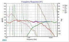
You make a valid point though I wouldn't describe the acoustic slopes as steep as that. Here's the raw frequency response of the JX150NG as measured mounted in the enclosure. I was unable to get anything resembling a smooth roll-off with less than 3rd order. I also listened to the unit in the raw and it sounded pretty rough up top.
Attachments
Last edited:
Sorry in advance for talking as if the Jordan is the main protagonist here but that is because of my lack of ribbon experience but I am more familiar with Jordans.
But E.J.Jordans employ a concept called "controlled cone break-up" to partially alleviate the problem of beaming commonly associated with cone drivers at higher frequencies than their cone diameter would suggest they could handle. One of the ways to make this work is the manufacturer recommends toe-in - it was not the intention to listen to them on-axis. Let's say it is designed to be listened to 15 degrees off-axis (I don't know the optimum angle) then naturally the on-axis response will have to be gently rising like what you measured. The gently rising on-axis will also (partially) compensate for the falling power response associated with a cone that is asked to play too high.
The way you built your cabinet, you already hit the jackpot - the ribbon and woofer may require different amounts of toe-in and your cabinet looks individually adjustable for each.
Now, I have not personally heard the JX150 - I am merely assuming family resemblance here, and just mentally assume it has the same great sonic signature as the more popular drivers of the brand, just that every aspect shifted one octave lower.
bentoronto
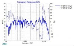
FR measurements were taken at 1 metre with a calibrated mic and no EQ using Holmimpulse, the frd files of these measurements used for the crossover simulations.
The treble filter is 2 element plus L pad, the bass filter is 3 element plus zobel.
The FR plot in my first post was smoothed 12/octave, the others are 24/octave.
Hi Tim,
Very nice design - thanks for sharing this with me. This reminds me of a speaker review by Keith Howard that I read many years ago where the mid & the tweeter were perched on top of the large bass enclosure - the description then of airy 3D sound captured my imagination and I tried to mimic this idea in some of my early designs and enjoyed the results.
Depending upon how much the main enclosure vibrates, I would be tempted to decouple the tweeter box from the main box with added mass & foam underneath - have heard good reports of this elsewhere.
Yes, air cored inductors in my experience give more a detailed & transparent midrange.
I never found yet any metal oxide resistor that sound cleaner that a good quality non-inductive wire wound resistor. If the values needed were small I would be tempted to make the resistors from manganin wire from wires.co.uk. Otherwise Mills wirewound might work for you.
WIRES.CO.UK
Mills | Hifi Collective
I am very tempted to try this idea with my own speakers
mike
Mike
Thanks for your comments and suggestions. I might try your suggestion using wire, particularly as I always find the values I settle on are never standard ones due to finding I have to adjust the treble to within 1/8dB until I get the balance that blends nicely.
To answer your other question I used Holmimpulse for FR and phase measurements. For impedance I used a scope and took multiple measurements the old way before tracing the plot from excel to a zma file to use in Xsim for the crossover, but I'm tempted to try a quicker method for this if there's a next time.
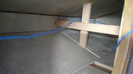
BTW, the enclosure doesn't vibrate due to the ceramic tiles lining the inside. Years ago I built a pair of speakers lined with 3/4 marble and cross braced every 4" with slate (can you believe it). The volume could be turned up to deafening levels with absolutely no discernable vibration. More recently I've found that 9mm floor tiles are just as effective but they need to be absolutely flat (many are not) if they are to be fixed with PVA which is my preferred option.
I've attached a picture of the inside of the enclosure.
Thanks for your comments and suggestions. I might try your suggestion using wire, particularly as I always find the values I settle on are never standard ones due to finding I have to adjust the treble to within 1/8dB until I get the balance that blends nicely.
To answer your other question I used Holmimpulse for FR and phase measurements. For impedance I used a scope and took multiple measurements the old way before tracing the plot from excel to a zma file to use in Xsim for the crossover, but I'm tempted to try a quicker method for this if there's a next time.
BTW, the enclosure doesn't vibrate due to the ceramic tiles lining the inside. Years ago I built a pair of speakers lined with 3/4 marble and cross braced every 4" with slate (can you believe it). The volume could be turned up to deafening levels with absolutely no discernable vibration. More recently I've found that 9mm floor tiles are just as effective but they need to be absolutely flat (many are not) if they are to be fixed with PVA which is my preferred option.
I've attached a picture of the inside of the enclosure.
Attachments
Your speaker is a fine achievement of design and execution, albeit abetted by your justified judgment to go with quality/expensive parts.FR measurements were taken at 1 metre....
Tough act to follow: now how do you bring your smarts to the less manageable world of trade-offs for your bass, which still has 3 8/aves to cover?
B.
PS
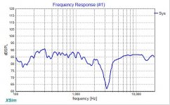
The subwoofers come in at 65Hz and the total response is pretty flat, albeit with four subs (one in each corner of the room) to iron out room modes. Please don't take anything below 250Hz on my earlier plots seriously. As I said before my interest was further up when I make those measurements and I think I used some gating in the measurements.
The subwoofers come in at 65Hz and the total response is pretty flat, albeit with four subs (one in each corner of the room) to iron out room modes. Please don't take anything below 250Hz on my earlier plots seriously. As I said before my interest was further up when I make those measurements and I think I used some gating in the measurements.
Be nice to see details.The subwoofers come in at 65Hz...
B.
- Status
- This old topic is closed. If you want to reopen this topic, contact a moderator using the "Report Post" button.
- Home
- Loudspeakers
- Multi-Way
- New Jordan JX150/A.C.Ribbon Design