You were talking about reduced excursion in the octave above tuning (utter twaddle since it is a rather well known fact that this is the region of maximum excursion in most vented box configurations, the one you posted self-evidently being no exception)....
Post 166? It's been a while but isn't the dashed blue line free air excursion? If so excursion would appear to be lower for the vented case, as well as closed box as I recall. The peak above tuning frequency is still substantially lower. What am I missing?
If you want to maximise dynamic range, that's certainly the way forward. There are limits to what unsupported wideband units, even ones with considerable travel available to them, can do.
Yes, that's what I was getting at - although I can certainly see the attraction of going for bass extension. It's the usual matter of choosing your own particular compromise, although I don't find the satellite/sub approach loses anything, other than floor space.
The gentleman was, I believe, claiming an MLTL with an F3 of 30Hz provides reduced driver excursion in the octave above Fb compared to enclosures tuned to a higher frequency. Which is nonsense, since in the vast majority of vented alignments (including the one for which he posted a displacement curve) maximum driver deflection occurs in this region. This octave naturally varies according to Fb. It is ironic though that the MLTL alignment I posted, which Mr. Dikovics has taken such an exception to, provides considerably lower driver deflection in the 60Hz - 100Hz region he originally stated he was concerned about, and indeed at all other frequencies < 150Hz, apart from the narrow region around Fb in the plot he posted in post 166. Of course, being tuned higher, my box doesn't have as much output in the low 30Hz regions, trading this off against a more balanced output higher up, a very flat impedance load, and very linear driver deflection. Here are the two displacement plots together, to ease comparisons:
Exactly Colin. I have no issues whatsoever with Mark's boxes; they are self-evidently perfectly valid enclosure designs of their type. But they are not the only valid type of MLTL alignment, and my purpose behind providing the one a couple of pages ago was to offer something a little different from the more usual run. For it, I decided to use an alignment I regularly employ, and known to be very effective. This is DIY: as you say, a range of box alignments to suit different preferences is usually nice to have, at least in my experience.
Last edited:
Disregard some of the above. I think we shall leave it that Mike and I have provided different box alignments. With any luck, a mod. might clean the thread up a bit, since it's a distraction from the Eikona, which isn't fair.
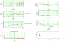
Sure. With the Eikona at any rate. A handful of FR plots attached; sans, with light & slightly more extensive damping. The other graphs assume the latter (0.5lbs ft^3 damping throughout). It doesn't go very low & has a bit of harmonic ripple, although in practice I'd expect that to be slightly less than indicated. Note that these are quasi-anechoic plots, that do not consider room-gain, amplifier output impedance, or the driver's actual rather than mathematical response. Carefully positioned, you may be able to get away without any compensation circuits since you've a free space baffle F3 of about 646Hz. The LF of the Eikona is rising somewhat at this point relative to where it's at between ~800Hz - 4KHz (see attached. Every little helps), & when it finally rolls off, the box may provide some balancing gain. Might be a bit of a dip between these points, but we're in the region dominated by the room in any case, where you're never going to get anything flat without masses of measurement & Eq.
If I'm honest, not great, but for what it is (a very small TL), I've seen worse.
Scott
I wondered if you would be able to do me a favour? Would you be able to see how both the Jordan EIKONA and the EAD E100HD may model in this cabinet?
Sure. With the Eikona at any rate. A handful of FR plots attached; sans, with light & slightly more extensive damping. The other graphs assume the latter (0.5lbs ft^3 damping throughout). It doesn't go very low & has a bit of harmonic ripple, although in practice I'd expect that to be slightly less than indicated. Note that these are quasi-anechoic plots, that do not consider room-gain, amplifier output impedance, or the driver's actual rather than mathematical response. Carefully positioned, you may be able to get away without any compensation circuits since you've a free space baffle F3 of about 646Hz. The LF of the Eikona is rising somewhat at this point relative to where it's at between ~800Hz - 4KHz (see attached. Every little helps), & when it finally rolls off, the box may provide some balancing gain. Might be a bit of a dip between these points, but we're in the region dominated by the room in any case, where you're never going to get anything flat without masses of measurement & Eq.
If I'm honest, not great, but for what it is (a very small TL), I've seen worse.
Attachments

Last edited:
Sure. With the Eikona at any rate, I've seen worse for what it is (a very small TL). A handful of FR plots attached; sans, with light & slightly more extensive damping. The other graphs assume the latter (0.5lbs ft^3 damping throughout). It doesn't go very low & has a bit of harmonic ripple, although in practice I'd expect that to be slightly less than indicated.
Thanks Scott, very much appreciated, scratch that design then...
The other graphs
Of note should be the impedance curve. Guys, time to break out your current amplifiers.
dave
it seems that no matter how many times it gets posted or who posts it, the vast majority of folks 'raised' on stupid high DF amps and T/S specs don't understand that a loudspeaker is just one link in the signal chain, so best overall performance requires designing it as part of a system that includes the room.
GM
GM
it seems that no matter how many times it gets posted or who posts it, the vast majority of folks 'raised' on stupid high DF amps and T/S specs don't understand that a loudspeaker is just one link in the signal chain, so best overall performance requires designing it as part of a system that includes the room.
GM
Amen!
And thanks...
it seems that no matter how many times it gets posted or who posts it, the vast majority of folks 'raised' on stupid high DF amps and T/S specs don't understand that a loudspeaker is just one link in the signal chain, so best overall performance requires designing it as part of a system that includes the room.
No argument from me.
")
Mike: the numbers come from the excursion graph you posted, and the graph for the box I did (part of the set I posted several pages ago). They simply list the numerical deflection values for each in mm in 10Hz increments. Everybody else seems to find it clear enough. The point was to demonstrate your apparent claim that a low-tuned vented box reduces exursion in the octave above Fb is (with certain exceptions) erroneous, and also that despite your professed desire to keep displacement down in the 60Hz - 150Hz region, the same Eikona drive unit in the enclosure I did, which you have taken such exception to, has considerably less travel in this zone. It also has less travel at lower frequencies, except in the narrow area (approximately 30Hz - 38Hz) around Fb in the enclosure for the excursion graph you posted. Normally you would be correct: a higher tuned box usually means a greater risk of uncontrolled driver oscillation when it is presented with a signal below Fb. However, it seems that you have failed to consider the high damping levels and relatively unreactive load of the enclosure I posted, resulting in quite linear excursion behaviour, clearly shown in the excursion and impedance plots I posted. That is one of the objectives behind using this alignment in the first place. You don't like it, which is fine, but unfortunately, you don't seem to understand it.
Dave's comment was perfectly solid, but perhaps not made entirely clear. A low tuning frequency does not automatically result in problems higher up. But like anything else it is a compromise. Assuming a quality alignment, these can include increased driver excursion, and thereby reduced LF dynamic range, along with higher distortion levels from both electromechanical and acoustical effects. Of course if a poor alignment is chosen, you can add that to the list too.
As for step-loss, I will make one last attempt to explain it to you.
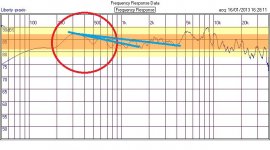
-Look at the published frequency response for the Eikona drive unit again. Does it look a smooth declining curve to you below 1KHz, as a mathematical IB derivation looks? No. We see that from 800Hz, down to ~250Hz, the response gradually rises relative to the midband. See the attached. I've drawn some lines in to show the average slope; I've even added a second one for a shallower slope if you prefer to view it in that fashion. This is the actual IB curve of the drive unit, presumably taken on an IEC baffle under anechoic conditions. Although not as extensive as the lift engineered into some (not all) of the MA drivers, it is sufficient to be useful.
-The baffle of the box I designed above is of 9in diameter, assuming 3/4in build material. That corresponds with a step-loss F3 of approximately 506Hz. Since the IB response of the Eikona drive unit is steadily rising at this point, and below, down to about 250Hz where it finally rolls away, this goes a reasonable way toward compensating for step-loss, particularly when you consider that below around 300Hz you will begin to get some help from the room under most practical conditions where a 5in wideband drive unit is likely to be used.
-The enclosure alignment I did provides reasonably broadband gain from Fb to around 150Hz. With average room-gain increasing in the < 300Hz region, in many situations you will thus obtain a reasonably balanced response without needing to resort to Eq, be it in the form of a shelving filter or other forms. There may be a dip in the response between ~150Hz and 250Hz, but in most cases the room will provide some help here, and since it dominates the response of a point-source speaker in this region, you are unlikely to get anything particularly flat anyway. Combined with our falling hearing acuity in the LF, you end up with a fairly practical combination. This is a rather well known and understood alignment quite commonly employed in pro-audio and elsewhere. So please stop claiming I need to 'do a little homework.'
Dave's comment was perfectly solid, but perhaps not made entirely clear. A low tuning frequency does not automatically result in problems higher up. But like anything else it is a compromise. Assuming a quality alignment, these can include increased driver excursion, and thereby reduced LF dynamic range, along with higher distortion levels from both electromechanical and acoustical effects. Of course if a poor alignment is chosen, you can add that to the list too.
As for step-loss, I will make one last attempt to explain it to you.
-Look at the published frequency response for the Eikona drive unit again. Does it look a smooth declining curve to you below 1KHz, as a mathematical IB derivation looks? No. We see that from 800Hz, down to ~250Hz, the response gradually rises relative to the midband. See the attached. I've drawn some lines in to show the average slope; I've even added a second one for a shallower slope if you prefer to view it in that fashion. This is the actual IB curve of the drive unit, presumably taken on an IEC baffle under anechoic conditions. Although not as extensive as the lift engineered into some (not all) of the MA drivers, it is sufficient to be useful.
-The baffle of the box I designed above is of 9in diameter, assuming 3/4in build material. That corresponds with a step-loss F3 of approximately 506Hz. Since the IB response of the Eikona drive unit is steadily rising at this point, and below, down to about 250Hz where it finally rolls away, this goes a reasonable way toward compensating for step-loss, particularly when you consider that below around 300Hz you will begin to get some help from the room under most practical conditions where a 5in wideband drive unit is likely to be used.
-The enclosure alignment I did provides reasonably broadband gain from Fb to around 150Hz. With average room-gain increasing in the < 300Hz region, in many situations you will thus obtain a reasonably balanced response without needing to resort to Eq, be it in the form of a shelving filter or other forms. There may be a dip in the response between ~150Hz and 250Hz, but in most cases the room will provide some help here, and since it dominates the response of a point-source speaker in this region, you are unlikely to get anything particularly flat anyway. Combined with our falling hearing acuity in the LF, you end up with a fairly practical combination. This is a rather well known and understood alignment quite commonly employed in pro-audio and elsewhere. So please stop claiming I need to 'do a little homework.'
Attachments
Last edited:
 I have taken a hatchet to what remained of the posts (some had already been deleted) from the last 18 hours.
 Debate Ideas. Do not attack people. If you do want to attack an idea make sure you have some credible reasoning to back you up.
BUT try to keep in mind that different people have different design goals and priorities. Building speakers is all about tradeoffs. Which tradeoffs you choose to live with is all part of the art.
I've ordered but there's a waiting list.
Ref Smallangryboy's design - it reminds me of a folded version of the off-set TL alignment, as described in George Augspurger's AES paper. I haven't tried that one but had a go at the chamber decoupled TL (aka Daline) that he mentions. It worked quite well with the JX92 and gave a compact, floor-standing enclosure, at the expense of bass extension. It was tuned to 70 or 80Hz, if I remember right.
Ref Smallangryboy's design - it reminds me of a folded version of the off-set TL alignment, as described in George Augspurger's AES paper. I haven't tried that one but had a go at the chamber decoupled TL (aka Daline) that he mentions. It worked quite well with the JX92 and gave a compact, floor-standing enclosure, at the expense of bass extension. It was tuned to 70 or 80Hz, if I remember right.
Right. Augspurger's alignments were essentially for creating something akin to a 'pure' TL, so F3 is usually higher than an equivalent reflex alignment, with the usual tradeoffs for & against. IIRC, they give a maximum 1dB dip at the 3rd harmonic & no more than 0.5dB variation above that.
BTW, there are some typographical errors in the tables contained in the AES paper, or at least the versions that I've seen that mess up the volume alignment. These were fixed for the somewhat expanded set of articles later published in Speaker Builder.
BTW, there are some typographical errors in the tables contained in the AES paper, or at least the versions that I've seen that mess up the volume alignment. These were fixed for the somewhat expanded set of articles later published in Speaker Builder.
You might not have done; it could have been fixed in other versions of the AES paper too. The SB articles (you only need the 3rd one) are the ones to use if in doubt though.
Either way, an Augspurger aligned TL is never going to be a bass monster because that wasn't what he was trying to do, but the optimum volume is of course preferable.
Either way, an Augspurger aligned TL is never going to be a bass monster because that wasn't what he was trying to do, but the optimum volume is of course preferable.
- Status
- This old topic is closed. If you want to reopen this topic, contact a moderator using the "Report Post" button.
- Home
- Loudspeakers
- Full Range
- New Jordan driver - preliminary details