Why do you think that. It is about how the horn is calculated.I'm not saying you cannot do it.. I'm saying it is not optimal.
BTW, I was comtemplating big woofers on the same baffle as mid and tweeters, and was reminded of a study done years ago by Adire Audio. It was related to the energy imparted to the cabinet by woofers. They found that mounting the woofer on the cabinet with a compliant gasket (think soft rubber ring), made a very significant difference to the amount of energy passed on to the cabinet. I still have the PDF on my pc (I'm texting from my phone). If you're interested I'll try to upload it, as Adire Audio is now long gone.
Enjoy,
Deon
Enjoy,
Deon
Hi Sirius
I had a look on my pc, butcannot find find that PDF. I remember it clearly, though, as the result surprised me. It was a woofer mounted in a sealed box. They took a waterfall plot, and then mounted the woofer on a compliant rubber gasket and took another waterfall plot. The 2nd plot showed a huge reduction in cabinet exitation. This surprised me as the energy generated into the box by the rear wave stays the same, but the results were undeniable.
Enjoy,
Deon
Thanks for looking for me. It's a real shame that Adire went under. They had some really nice drivers that I never had the opportunity to purchase. Great company.
I've been brainstorming some, and I think I've come up with something that will keep the woofers energy from exciting the mid/tweet.
Do you have an example of such a compliant rubber gasket? I can't picture it at the moment.
I've been brainstorming some, and I think I've come up with something that will keep the woofers energy from exciting the mid/tweet.
Do you have an example of such a compliant rubber gasket? I can't picture it at the moment.
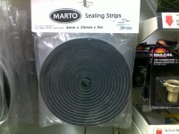
I don't, but I saw something at a local hardware store that looks like it will work. It's some kind of foam-rubber sealing strip. It is similar in some ways to double-sided tape, but the core is a dark grey type of foam-rubber. It sold in long strips that are rolled up. I need to go there tomorrow, so I'll check what they call it over here (in South-Africa), and I'll let you know.
Enjoy,
Deon
Enjoy,
Deon
I gave this some more thought, and what I would suggest is that you suspend the woofers by their magnets, similar to what it looks like you already did. If they are fully suspended by their magnets, and the woofers' vibrations are sinked through that connection, then you can use the doorseal to mount them to the baffle. Then you could easily mount the mids and tweets on the same baffle with almost zero interference from the subs.
Enjoy,
Deon
PS. IIRC the rubber that Adire used was something like that made by Deflex- something not too thick but made for mounting drivers. So I think thick doorseal would make for an adequate replacement.
Enjoy,
Deon
PS. IIRC the rubber that Adire used was something like that made by Deflex- something not too thick but made for mounting drivers. So I think thick doorseal would make for an adequate replacement.
I had a look at my local hardware store, and I found that sealing strip again. Have a look at the attached pic. They had it in 3mm (0.12''), 6mm (0.24''), 10mm and 12mm thicknesses. I would suggest that the 6mm is the thickest strip I would suggest using with the woofers.
Attachments
That's what I had in mind as well. Thanks a lot!
I have also found another potential solution as I currently do not like the magnet mounts I have made - I don't trust them with the weight of the woofers (~16kg each).
I am thinking about suspending the woofer mounting frame between two baffles (padded with the gasketing tape), basically placing long bolts through the two baffles and the frame of the woofer. This will allow the woofer to vibrate back and forth at will and minimally affecting the baffle. I am thinking about placing a magnet support in the back due to the weight. What do you think?
I'm totally clear about what you want to do, but I would be careful of too large a baffle behind the driver (unless you want a more cardoid radiation pattern). How long are those magnets? How about solid wooden blocks, cut in three pieces, and round holes (well, half moons cut in each for the magnets) cut in each. The firts block from the floor, with a half moon for the bottom of the first magnet. in the middle the second block, half moons on either end for the top of the lower woofer magnet and the bottom of the upper woofer magnet. Thord block on top. The blocks must be wider than the magnets as they will be clamped together with four 40'' threaded rods (two per side). The blocks should be heavy and the half-moon cutouts lined with sealing strip. The bottom block can have an additional extra heavy and wide (and deep) foot to help keep the woofers steady. Just a thought. ")
Enjoy,
Deon
Enjoy,
Deon
Make the foot in a cross pattern. Think four triangular shaped pieces, one on each side. That will provide both weight and stability. Make the magnet support pillar 9.5'' by 9.5''. Router a 1.5'' deep hole for the magnets. I would still cut the pillar in three pieces as above, and connect them with rods running from top to bottom. The triangular foot pieces can be say about 12'' tall by 12'' deep by 9.5'' wide for the side and rear pieces, and 9.5'' by 9.5'' and 9.5'' for the piece behind the woofer.
Hi Ben
Here is my idea in more detail. I have thought about it, and gotten an idea of how to make it.
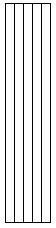
Step 01: Get a number of 2" x 4" wooden planks, ones that are already planed smooth. Then cut them to a length of about 45", but all must be the same length. You will need seven (7) pieces in total for each side, so fourteen (14) pieces in total. Then you glue/laminate five pieces side-by-side, gluing the 4" sides to each other. This should leave you with a wooden pillar measuring 10" wide by 4" deep, and by 45" tall (or whatever height you chose). See: Woofer-pillar step 01.jpg.
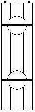
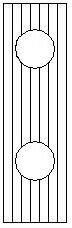
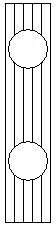
Step 02: Use a router to cut two holes of 9.5" diameter and 1.5" deep into the pillar. To calculate the height of the holes, work out what the mid-point for each driver on the baffle is going to be. That will then be the mid-point of the hole. That means that the holes will not go through the pillar, which will help with rigidity and weight. See: Woofer-pillar step 02.jpg.
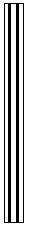
Step 03: So far you have only used ten of the fourteen pieces of cut lumber. Using a router again, router two straight grooves down the one side of the plank (VERY important that they are straight, as you will see later on). They must not be too deep. I would say not more than 1" deep. The depth will depend on the diameter of the threaded rod that you will be using. These are going to be the grooves that they run in. See: Woofer-pillar step 03.jpg.
Step 04: Glue the new pieces to the existing pillar with the grooves on the inside. See: Woofer-pillar step 04a.jpg; Woofer-pillar step 04b.jpg. Woofer-pillar step 04b.jpg is the view from the top.
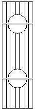
Step 05: Now cut the pillar in three pieces. The lines for the cut must be down the middle of each hole. See: Woofer-pillar step 05.jpg.
Step 06: Put the threaded rod into the grooves on the sides of the pillar. Line the insides of each hole with the sealing strip. Now the pillars are almost ready for the woofers to be mounted. See: Woofer-pillar step 06.jpg.
Step 07: The woofers can now be test fitted to see if all is working well. See: Woofer-pillar step 07.jpg.
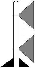
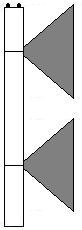
Step 08: You were worried about the foot, i.e. stability of the pillar. This is what I meant by triangular pieces of wood. I have however reconsidered the cross-pattern idea. The pillars will be wide enough not to be unstable in the side-ways direction, something for which the front baffle will also help, but forward and backward stability will still be compromised. Therefore I now suggest only two triangular pieces- on on the front and one in the back. the reason for the shape will become obvious in the next step. See: Woofer-pillar step 08.jpg for an idea of what they'll look like.
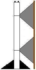
Step 09: Now mount the triangular feet to the front and rear baffle. I hope my meaning will be clear out of the drawing. See: Woofer-pillar step 09.jpg.
Step 10: Now the front baffle can be mounted. Since the most of the woofers' vibrations will be sinked into the floor via the magnet-pillar, there will be a minimum of vibration translated to the baffle. If you then mount the woofers using the sealing strip, then the woofers' influence on the front baffle should be almost non-existent, no matter how hard they work. See: Woofer-pillar step 10.jpg (in the next post- I reached my max number of attachments).
Hope this clears things up. This is a huge project should you take it on, and I won't blame you if you try and find an easier way, but this would be my way.
Enjoy,
Deon
Here is my idea in more detail. I have thought about it, and gotten an idea of how to make it.
Step 01: Get a number of 2" x 4" wooden planks, ones that are already planed smooth. Then cut them to a length of about 45", but all must be the same length. You will need seven (7) pieces in total for each side, so fourteen (14) pieces in total. Then you glue/laminate five pieces side-by-side, gluing the 4" sides to each other. This should leave you with a wooden pillar measuring 10" wide by 4" deep, and by 45" tall (or whatever height you chose). See: Woofer-pillar step 01.jpg.
Step 02: Use a router to cut two holes of 9.5" diameter and 1.5" deep into the pillar. To calculate the height of the holes, work out what the mid-point for each driver on the baffle is going to be. That will then be the mid-point of the hole. That means that the holes will not go through the pillar, which will help with rigidity and weight. See: Woofer-pillar step 02.jpg.
Step 03: So far you have only used ten of the fourteen pieces of cut lumber. Using a router again, router two straight grooves down the one side of the plank (VERY important that they are straight, as you will see later on). They must not be too deep. I would say not more than 1" deep. The depth will depend on the diameter of the threaded rod that you will be using. These are going to be the grooves that they run in. See: Woofer-pillar step 03.jpg.
Step 04: Glue the new pieces to the existing pillar with the grooves on the inside. See: Woofer-pillar step 04a.jpg; Woofer-pillar step 04b.jpg. Woofer-pillar step 04b.jpg is the view from the top.
Step 05: Now cut the pillar in three pieces. The lines for the cut must be down the middle of each hole. See: Woofer-pillar step 05.jpg.
Step 06: Put the threaded rod into the grooves on the sides of the pillar. Line the insides of each hole with the sealing strip. Now the pillars are almost ready for the woofers to be mounted. See: Woofer-pillar step 06.jpg.
Step 07: The woofers can now be test fitted to see if all is working well. See: Woofer-pillar step 07.jpg.
Step 08: You were worried about the foot, i.e. stability of the pillar. This is what I meant by triangular pieces of wood. I have however reconsidered the cross-pattern idea. The pillars will be wide enough not to be unstable in the side-ways direction, something for which the front baffle will also help, but forward and backward stability will still be compromised. Therefore I now suggest only two triangular pieces- on on the front and one in the back. the reason for the shape will become obvious in the next step. See: Woofer-pillar step 08.jpg for an idea of what they'll look like.
Step 09: Now mount the triangular feet to the front and rear baffle. I hope my meaning will be clear out of the drawing. See: Woofer-pillar step 09.jpg.
Step 10: Now the front baffle can be mounted. Since the most of the woofers' vibrations will be sinked into the floor via the magnet-pillar, there will be a minimum of vibration translated to the baffle. If you then mount the woofers using the sealing strip, then the woofers' influence on the front baffle should be almost non-existent, no matter how hard they work. See: Woofer-pillar step 10.jpg (in the next post- I reached my max number of attachments).
Hope this clears things up. This is a huge project should you take it on, and I won't blame you if you try and find an easier way, but this would be my way.
Enjoy,
Deon
Attachments
-
 Woofer-pillar step 09.JPG4.6 KB · Views: 33
 -
 Woofer-pillar step 08.JPG1.1 KB · Views: 207
 -
 Woofer-pillar step 07.JPG3.9 KB · Views: 35
 -
 Woofer-pillar step 06.JPG5.3 KB · Views: 27
 -
 Woofer-pillar step 05.JPG5.3 KB · Views: 161
 -
 Woofer-pillar step 04b.jpg1.1 KB · Views: 208
 -
 Woofer-pillar step 04a.jpg3.9 KB · Views: 171
 -
 Woofer-pillar step 03.JPG2.1 KB · Views: 187
 -
 Woofer-pillar step 02.JPG4 KB · Views: 193
 -
 Woofer-pillar step 01.JPG3.5 KB · Views: 191
Quick correction: the diameter of the holes detailed in Step 02 will NOT be 9.5" diameter. They must be calculated thus: (the diameter of the magnet to be fitted in the hole) + (half the thickness of the sealing strip to be used). That way when the magnet is fitted, the sealing strip will be compressed to half of it's thickness, therefore providing positive grip yet still providing some form of vibration damping.
Enjoy,
Deon
Enjoy,
Deon
That looks like a very sturdy way of doing things! We were pretty much thinking the same thing. I haven't gotten much further today - went grocery shopping, then to a memorial service, then some yard work.Well - I did get around to taking my first measurements today
All the stuff showed up today (three day priority from CA to NC??!!). I couldn't Speaker Workshop to install and am having problems with Visual Analyzer so ARTA is what I played around with some. Took a little bit as this is the first time I'm using this kind of equipment and software, however what I can tell you 100% is that we're bass heads . I'm using the ECM8000 from behringer to measure and I'm not sure what response curve it has below 100Hz, however I seem to be at 10-15dB+ in the bottom end. The top end for the tweeter is pretty level considering I'm only using the front wave (not a true dipole). There are some pretty good peaks and valleys, one very large one.Now if only I can figure out how to get screen shots without using "Print Screen" that'd be cool
!Seeing the response, I have definitely decided to go with a minidsp (at least a 2x4) and get two Topping TP20-MK2s for the B&C mid and tweeter (~13Wrms should be fine right?).
Mirek's Free Windows SoftwareNow if only I can figure out how to get screen shots without using "Print Screen" that'd be cool
Really, really good screen cap software - and free!
- Status
- This old topic is closed. If you want to reopen this topic, contact a moderator using the "Report Post" button.
- Home
- Loudspeakers
- Multi-Way
- New forum member, new OB project