Hi Maiky,
I'm interested in knowing more about the counter-intuitive results you saw through your experiments with cabinet contrsuction.
I have generally held to the view (without any objective evidence) that for low frequency enclosures I try and push the resonances as high as possible, preferrably out of the pass band. While for mid frequency boxes I try to make the panels as thin as possible laminated with lossy material to drive the resonances below the pass band.
I think you're right about dipole operation only being useful in the lower frequency ranges. Once a driver starts operating in it's cone breakup region I can't imagine dipole operation being possible. In any case the wavelengths become too short to stop the room causing random phase variations again inhibiting dipole operation. I would guess it's only useful to around 500Hz or so with typical drivers and baffle sizes.
I only plan to operate as a dipole up to the bottom of the ATC passband at around 400Hz. Dipole operation should also help me to avoid many of the box resonance issues. The plan is simply to make the baffle quite thick 30-40mm and relatively small and to rigidly mount the drivers. Compliant mounting is probably better but too difficult.
Cheers,
Ralph.
Hi Ralph,
Sorry for my late reply, I am fairly busy...
I’ll try to explain the best I can my small contribution to acoustical behaviour of loudspeakers. As an introduction I would say that conclusions are only confirmations of theory derived hypothesis and some are actually surprises one refers to audiophile wisdom. Those conclusions are facts confirmed by measurements. I use at first a laser interferometer (Polytec) to make cartography of a small bookshelf speaker. The tight spatial sampling (1500 points) enabled me first to “see actual resonances” up to 3000Hz (!) and in a second time, to run a BEM code to calculate acoustical radiation for several frequencies. Then I used BK accelerometers and Matlab driven Stanford analyser to extend my conclusions over a tower shape speaker. I also used an Ometron scanner as reference. I have also undergone listening tests.
Anyway, in every cases any volunteer to do measurements must keep in mind that:
1. Simple vibration measurements cannot account for any precise acoustical results. There no simple operator to transpose accelerometer out-put into dB SPL. The geometry of pattern’s deformation is preponderant in is acoustic radiation of each resonance.
2. Every result is dependent to the case under test. It not trivial to infer result for another case than the one examined
So here are the results. They are precise enough, for a clever person, to enable to reach good results.
Mass is not the panacea and rises many issues. (how to dissipate the energy stored within the mass?)
Stiffness and amortization are the main factors.
The solutions are highly frequency and geometry dependant.
The addition of several effective treatments often leads to worst results than the ones of each treatment used alone. Combined treatment can lead to worst results than no treatment at all.
Speakers’ behaviour, as any structure, is described by global resonances.
So treatments focusing only on one side/panel of a speaker are useless.
Cross on one panel has no effect both in terms of vibrations and radiation.
Treatments dealing with several panels are far more effective.
Geometry of the speaker must be taken into account to elaborate the treatment.
A cross that links the four panels amply the vibrations in the wider range (it better the coupling between the high vibrating fields…)
The front panel is the key of vibrations.
Priority should be to treat it.
Mass addition is not the best solution.
Important couplings are: drivers/front panel and front panel/rest of the enclosure.
Some more feature I verified against my will….
Always glue the panel together screws are springs….
Coupling speaker/ground or speaker/stand + stand/ground is very important
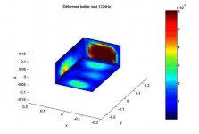
See the kind of image I obtained with cartography(sorry for the poor quality...)
Cheers
Mickael
Sorry for my late reply, I am fairly busy...
I’ll try to explain the best I can my small contribution to acoustical behaviour of loudspeakers. As an introduction I would say that conclusions are only confirmations of theory derived hypothesis and some are actually surprises one refers to audiophile wisdom. Those conclusions are facts confirmed by measurements. I use at first a laser interferometer (Polytec) to make cartography of a small bookshelf speaker. The tight spatial sampling (1500 points) enabled me first to “see actual resonances” up to 3000Hz (!) and in a second time, to run a BEM code to calculate acoustical radiation for several frequencies. Then I used BK accelerometers and Matlab driven Stanford analyser to extend my conclusions over a tower shape speaker. I also used an Ometron scanner as reference. I have also undergone listening tests.
Anyway, in every cases any volunteer to do measurements must keep in mind that:
1. Simple vibration measurements cannot account for any precise acoustical results. There no simple operator to transpose accelerometer out-put into dB SPL. The geometry of pattern’s deformation is preponderant in is acoustic radiation of each resonance.
2. Every result is dependent to the case under test. It not trivial to infer result for another case than the one examined
So here are the results. They are precise enough, for a clever person, to enable to reach good results.
Mass is not the panacea and rises many issues. (how to dissipate the energy stored within the mass?)
Stiffness and amortization are the main factors.
The solutions are highly frequency and geometry dependant.
The addition of several effective treatments often leads to worst results than the ones of each treatment used alone. Combined treatment can lead to worst results than no treatment at all.
Speakers’ behaviour, as any structure, is described by global resonances.
So treatments focusing only on one side/panel of a speaker are useless.
Cross on one panel has no effect both in terms of vibrations and radiation.
Treatments dealing with several panels are far more effective.
Geometry of the speaker must be taken into account to elaborate the treatment.
A cross that links the four panels amply the vibrations in the wider range (it better the coupling between the high vibrating fields…)
The front panel is the key of vibrations.
Priority should be to treat it.
Mass addition is not the best solution.
Important couplings are: drivers/front panel and front panel/rest of the enclosure.
Some more feature I verified against my will….
Always glue the panel together screws are springs….
Coupling speaker/ground or speaker/stand + stand/ground is very important
See the kind of image I obtained with cartography(sorry for the poor quality...)
Cheers
Mickael
Attachments
Thanks for the insights Mickael,
Yes, I can see your point about extra mass, once in motion, will take extra time to release it's kinetic energy. I wonder if the additional mass will also be more resistant to acceleration however. In the steady state the extra mass won't help, but it may for transients. Was your testing performed with continuous tones?
Also increasing mass will tend to push resonces lower in frequency which may be beneficial for midrange enclosures.
Increasing stiffness will tend to push resonances higher in frequency. This may be beneficial for low frequency enclosures. But I'm not sure I understand what you mean by amortisation. Can you please explain this term?
If I understand you correctly you are suggesting that increased mass brings with it increased stiffness, having contradictory influences on resonant frequencies, and a tendancy for greater energy storage.
I agree that the baffle is the key component in an enclosure. It radiates directly towards the listener and can benefit from being decoupled from the driver at low frequencies.
I assume you have seen the paper from TAD that describes a basic experiment in driver decoupling.
Your assertion that bracing can do more harm than good is interesting, but I'm not sure I understand your comment completely. "A cross that links the four panels amply the vibrations in the wider range (it better the coupling between the high vibrating fields…)"
When you say wider range, do you mean a wider frequency spectrum?
Cheers,
Ralph
There's one material where mass and stiffness is unquestionable and that is concrete. Its horrible to work with but simply unrivalled resonance damping for the costs involved, though there is ultimately better material at a price. Try a 3" thick concrete baffle and you'll not only break your back but won't have to worry about any cabinet borne resonances.
Its impratical of course and I tend to simply use MDF with matrix bracing, 1" thick walls with 3-4" baffles. It works and its easy to actually work with.
I think you can over analyse the properties of the cabinet but its a greater folly to under-engineer a cabinet.
Its impratical of course and I tend to simply use MDF with matrix bracing, 1" thick walls with 3-4" baffles. It works and its easy to actually work with.
I think you can over analyse the properties of the cabinet but its a greater folly to under-engineer a cabinet.
Hi Ralph,
Hi Shin,
For my measurements I used white and pink noise. So it is not a steady state signal.
It seems that you are not a total newbie, but let me put in plain words some facts. I prefer explain with plate’s theory, it is way easier to understand…
If I refer to the theory it is possible to roughly explain the behaviour of plates by regarding 3 totally disconnected parameters:
Mass: increase it and resonances will go lower in Freq
Stiffness: increase it and resonance will go higher in Freq
Amortization: increase it and modes will have the shortest life. It is represented by the internal coefficient “epsilon». Amortization enables any material to dissipate the energy of vibration. The typical example is the car. There is a spring and a shock absorber, w/o the absorber the car is like a trampoline (or a typical car from US ;-). The same way for the Q of a sealed box.
It is a bit more complex than onlu this, but think about the two species within the tweeters metal (hard) domes and cloth (soft) domes, see their frequency response.
Anyway the entire frequency domain is split into 3 areas depending on each material specs as far as vibrations are concerned:
Low frequencies: stiffness driven
High frequencies: mass driven
Between these two asymptotes: resonances (and thus amortization) are predominant. As an example take a bell: the raw material is very heavy, very stiff but has a very weak amortization. Don’t we say: “ring like a bell”…. The only way for the bell to dissipate its energy is acoustical radiation and as the energy radiated this is very (very) small, the bell keeps of ringing a long time after been knocked. The concrete is more or less like a bell that why when you live on the 10th floor and you are knocking on a nail on the wall your neighbour of the 2nd floor wants to kill you.
But if you increase the mass to a point that low frequency of music spectrum is a high frequency for the material you have a good solution, valid for all the audible range and a speaker witch weight tons. I repeat a building wall is not heavy enough…. I do insist to say that all solution is only valid for a certain range of frequencies!
Now think of a light, very stiff and heavily amortized panel, what would be its behaviour?
I have said that the acoustic radiation is heavily geometry dependent, if you link the centre of each panel with a cross, as an example, you enable some panels to put other panels under vibrations…
It highly increases the radiation on a wide spectrum of frequencies.
I read a paper dealing with driver/front panel interface. I wonder if it was from Pioneer, I could actually be from TAD as TAD = Pioneer! It was very interesting indeed. I would rather speak about coupling the driver with the cabinet, because decoupling is another issue. I have results I cannot issue. The front panel is weak because of the holes of drivers. So it is easily put under vibrations because of the reaction due to cone motion and then it put all the cabinet under constrains… let’s imagine a piece of wood that links the back of the driver to the rear panel.
I don’t think you can actually over analyse a cabinet, you just can misanalyse it.
Some more tweaks:
When you want to add amortization (felt as an example), always use it under shear constrain, if you don’t you only basically add extra mass.
For a front panel use al least two layers of different material, I let you guess which ones and don’t hesitate to over size the quantity of glue you use…
@+
Maiky
Hi Maiky,
I now understand what you mean by amortisation now. Damping!
Clearly, increasing damping will reduce the panel's ability to radiate energy as sound. The energy is simply lost in the material as heat. I understand that at the frequency extremes, resonant behaviour does not occur and that the panel is either stationary by virtue of it's mass or moving in sympathy with the driver frame by virtue of it's stiffness.
But I think most people associate adding mass with adding thickness. Adding thickness increases stiffness as well as adding mass. In fact stiffness increases with the 3rd power of thickness, so even a small increase in mass (thickness) is associated with a large increase in stiffness. Thus it is possible to reduce the range of frequencies a panel is capable of radiating at by increasing thickness. The down side, as you point out, is that if damping is poor we end up with a structure radiating all of its energy in a narrow band of frequencies and it rings like a bell.
I agree with Shin in that I think concrete is a good material for cabinet construction. It has to be used in thick slabs which makes it very stiff. It is also well damped if used without too much reinforcement and not held under tension.
I take your point about the effect of bracing between opposite panel faces causing the rear panel to radiate more than if it had no coupling to the baffle. But I wonder if the increase in rear panel radiation is offset to some degree by the reduction in baffle radiation if the coupling is sufficiently rigid. A flexible coupling cannot hope to equalize the forces acting between panels, but a perfectly rigid brace should be able to force something like dipole operation of the front and rear panels at low frequencies, thus reducing the overall power radiated into the room by the enclosure in the same way a dipole driver does.
Did your measurements look at total power radiated by an enclosure or the contributrion of individual panels? Were you cross braces very stiff or somewhat flexible?
Cheers,
Ralph.
- Status
- This old topic is closed. If you want to reopen this topic, contact a moderator using the "Report Post" button.
- Home
- Loudspeakers
- Multi-Way
- New Floorstander Project