Flare's multi-way speaker is nice looking - maybe a brave foam-core builder could give the idea a whirl

An externally hosted image should be here but it was not working when we last tested it.
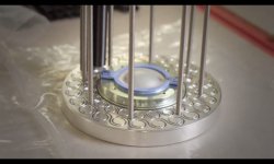
Here is the compression driver's housing for that model, as grabbed from one of Flare Audio's videos (the link I posted up before). The grooves in the metal plate show the shape of the 3-D printed cavities, the type that are detailed in one of the patents I linked to (first on I think).
The shape looks like a circular space which opens up into a gap into another, larger circular space..
The shape looks like a circular space which opens up into a gap into another, larger circular space..
Attachments
This looks like their headphone design as screen-grabbed below - would explain the wire or whatever it is in the diagram, part 171.
I would like to design something like that to 3D print and modify a pair of headphones by creating new back enclosures to directly replace the originals, perhaps on my Denon D5000s.
Attachments
Last edited:
How do they deal with the baffle diffraction caused by drivers mounted in the center of a circular baffle?
The "Zero 5" has an outer diameter of 276mm which should put the worst of the diffraction peaks and dips in the critical 1-5kHz range. Diffraction from baffle edges
The "Zero 5" has an outer diameter of 276mm which should put the worst of the diffraction peaks and dips in the critical 1-5kHz range. Diffraction from baffle edges
How do they deal with the baffle diffraction caused by drivers mounted in the center of a circular baffle?
The "Zero 5" has an outer diameter of 276mm which should put the worst of the diffraction peaks and dips in the critical 1-5kHz range. Diffraction from baffle edges
Good question. They probably don't - it's a design that will be full of diffraction peaks/dips up to 5dB to 6dB. I found this out for myself first-hand. It's a real effect and it can screw up a perfectly flat response driver (like a TC9FD or SS 10F/8424).
Here is some data from Linkwitz for a 6in dia round baffle:
Diffraction from baffle edges
wondered about the wire/tail  - for a speaker, is their sb12a the simplest approach to build? How well do the "swirly" chambers work in reality at various levels? Flare certainly seems serious with the quality of their stuff.
(btw - aren't their ear protectors a re-hash of the 1970's Sonic Ear Valve?)
- for a speaker, is their sb12a the simplest approach to build? How well do the "swirly" chambers work in reality at various levels? Flare certainly seems serious with the quality of their stuff.(btw - aren't their ear protectors a re-hash of the 1970's Sonic Ear Valve?)
the original Sonic Ear Valve worked very well - I don't know if the current incarnation is much good - - wish I could have kept them in my ears when standing next to a drumkit and guitar amplifiers
Lee Sonic Ear Valve
Lee Sonic Ear Valves
Modern version
http://www.interstatemusic.com/3273...mpaign=gbase&gclid=CJvQutPk79ECFUW1wAodhMcI8g
Lee Sonic Ear Valve
Lee Sonic Ear Valves
Modern version
http://www.interstatemusic.com/3273...mpaign=gbase&gclid=CJvQutPk79ECFUW1wAodhMcI8g
Last edited:
I found an interesting muffler company which may be using the same principles as we see in the vortex flare enclosures.
These mufflers are high-flow and low backpreasure, by design, which makes sense if you want to emulate an infinite baffle, in an enclosure.
"SpinTech's patented technology is based on the second law of thermodynamics or entropy. The entropy of a system relates to organization of the system. Sound energy actually represents a form of organized energy in the sense that the molecules of air or gas vibrate together in a unified way. (On a microscopic level these gas molecules bounce off one another like billiard balls). Heat energy is also the vibration of molecules. Heat and sound energy are very much the same except for their organization, or entropy. Heat is a completely randomized molecular vibration, while a sound wave is an organized wave front of vibration.
Flow routing is based on advanced fluid mechanics technology. Vortices are sustained inside of the muffler's spin sound traps. Vent holes are placed in an area where the case wall and the sound trap form a venturi. As gas flows over the vent holes, the reduced pressure extracts gas out of the trap. Incoming exhaust from the main exhaust flow stream refills the trap and maintains the vortex motion that promotes the conversion of sound to heat"
So it seems that the theory is quite simple- spinning sound energy creates attenuation. What's not so simple is how much, and at what flow rates.
I'd imagine staying at or under 11-17 m/s (a common rule of thumb for bass reflex enclosures) is a good starting point for flow rates at an exit terminus.
An externally hosted image should be here but it was not working when we last tested it.
.jpg)
These mufflers are high-flow and low backpreasure, by design, which makes sense if you want to emulate an infinite baffle, in an enclosure.
"SpinTech's patented technology is based on the second law of thermodynamics or entropy. The entropy of a system relates to organization of the system. Sound energy actually represents a form of organized energy in the sense that the molecules of air or gas vibrate together in a unified way. (On a microscopic level these gas molecules bounce off one another like billiard balls). Heat energy is also the vibration of molecules. Heat and sound energy are very much the same except for their organization, or entropy. Heat is a completely randomized molecular vibration, while a sound wave is an organized wave front of vibration.
Flow routing is based on advanced fluid mechanics technology. Vortices are sustained inside of the muffler's spin sound traps. Vent holes are placed in an area where the case wall and the sound trap form a venturi. As gas flows over the vent holes, the reduced pressure extracts gas out of the trap. Incoming exhaust from the main exhaust flow stream refills the trap and maintains the vortex motion that promotes the conversion of sound to heat"
So it seems that the theory is quite simple- spinning sound energy creates attenuation. What's not so simple is how much, and at what flow rates.
I'd imagine staying at or under 11-17 m/s (a common rule of thumb for bass reflex enclosures) is a good starting point for flow rates at an exit terminus.
Last edited:
I'd like to give it a whirl - what might be simple implementation ? will Akabak sim the Vortex box?
An externally hosted image should be here but it was not working when we last tested it.
when you have time X, lets see an Akabak prediction. There's some vortex action I think in a classic Karlson's front chamber which can be seen with smoke under sine drive (high pressure at the top - low at the widest part of the aperture)- of course that could come from too small a vent as in some X15 cabinets. K15 is very well behaved had had far less vent velocity and cone excursion below fb than a reflex the size of K15's rear chamber and K15's tuning determined by Zmin between the two LF peaks.
I can't see how a muffler, or similar, could work for audio. The air etc emitted from an exhaust, with or without a muffler, is more akin to DC pulses being ejected out of it. Whereas, the air in a port/s in a speaker cabinet are AC sinewaves.
Would it matter? A driver can try its best to give out a square wave with it's own physical limitations if that's the signal it's trying to recreate. Similarly a piston can't accellerate from 0 to max speed to 0 again instantly i.e. the air pressure and airflow will be AC. Still a pressure wave whether a DC pulse or smooth sine wave.
Or perhaps you're talking about air flow being in one direction only? In which case you either replicate the chambers facing the opposite flow too or you make the chambers with two openings i.e exactly like the Flare Audio's ones.
Hey guys another crazy idea. Sound can only travel if it has mass to push against.. so can we possibly see sound as organized particular transmission?
Point being, when I think of absolute entropy, the first thing I think of is absolute zero, which is where mass loses so much heat that the particles don't vibrate anymore.
Then I got to thinking.. if sound can be seen as particles, then all we need to do is use a vortex to seperate particles from air- make the sound particles "dead"! Then it hit me that this is exactly how the new cyclonic vacuum's work.
Looking at a cutaway diagram of a cyclonic vacuum's separation chamber, you can see it's designed for airflow going into one direction- no good for us. Although, there is the possibility that if we mirror the "input" to the other side, we create a vortex in both directions, similar to Flare Audio's approach. Then we have the problem of no pressurization due to the top "output", and without pressurization- I theorize no spin.
So we simply eliminate the top "output", and we are left with a modification on Flare Audio's design. Basically a cone with an input and output, angled to spin the airflow in the same direction, and placed at opposite ends of the base of the cone. This should be much easier to approximately model than the spinning Venturi muffler design!

One final possible optimization- to minimize disturbance of the vortex, the input and output terminus should be flush to the cone's walls- kinda like a NACA duct shape.
Point being, when I think of absolute entropy, the first thing I think of is absolute zero, which is where mass loses so much heat that the particles don't vibrate anymore.
Then I got to thinking.. if sound can be seen as particles, then all we need to do is use a vortex to seperate particles from air- make the sound particles "dead"! Then it hit me that this is exactly how the new cyclonic vacuum's work.
Looking at a cutaway diagram of a cyclonic vacuum's separation chamber, you can see it's designed for airflow going into one direction- no good for us. Although, there is the possibility that if we mirror the "input" to the other side, we create a vortex in both directions, similar to Flare Audio's approach. Then we have the problem of no pressurization due to the top "output", and without pressurization- I theorize no spin.
So we simply eliminate the top "output", and we are left with a modification on Flare Audio's design. Basically a cone with an input and output, angled to spin the airflow in the same direction, and placed at opposite ends of the base of the cone. This should be much easier to approximately model than the spinning Venturi muffler design!
One final possible optimization- to minimize disturbance of the vortex, the input and output terminus should be flush to the cone's walls- kinda like a NACA duct shape.
An externally hosted image should be here but it was not working when we last tested it.
Last edited:
- Status
- This old topic is closed. If you want to reopen this topic, contact a moderator using the "Report Post" button.
- Home
- Loudspeakers
- Full Range
- New enclosure design- Vortex by Flare Audio