Thanks phase,
have paired it with a diy fully-differential mc phono stage and a new Ortofon cartridge. Even changed the Clearaudio RCAs to differential micro twinax connectors and now have a fully balanced path from transducer to PA.
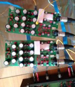
The phono stage is based around JCs fully-differential folded-cascode input stage (as per Vendetta) but uses low-noise smd bipolar toshibas into an OPA1632, dc servoed. DC-coupled from cartridge to my Proacs")
For the phono stage power supply I have used multiple cascaded floating differential RCs for filtering and open-loop shunt regulation via amplified zeners. DC input: 48V, regulated output: +-15V (also used by Sutherland Engineering).
Cheers,
hollow
have paired it with a diy fully-differential mc phono stage and a new Ortofon cartridge. Even changed the Clearaudio RCAs to differential micro twinax connectors and now have a fully balanced path from transducer to PA.
The phono stage is based around JCs fully-differential folded-cascode input stage (as per Vendetta) but uses low-noise smd bipolar toshibas into an OPA1632, dc servoed. DC-coupled from cartridge to my Proacs
For the phono stage power supply I have used multiple cascaded floating differential RCs for filtering and open-loop shunt regulation via amplified zeners. DC input: 48V, regulated output: +-15V (also used by Sutherland Engineering).
Cheers,
hollow
Attachments
Last edited:
The phono stage is based around JCs fully-differential folded-cascode input stage (as per Vendetta) but uses low-noise smd bipolar toshibas into an OPA1632, dc servoed. DC-coupled from cartridge to my Proacs
For the phono stage power supply I have used multiple cascaded floating differential RCs for filtering and open-loop shunt regulation via amplified zeners. DC input: 48V, regulated output: +-15V (also used by Sutherland Engineering).
Thanks, Hollow-man, for sharing this project.
Of course I'm curious about that phono stage you used, as well as its power supply. Planning to show it here too?
carlmart,
I think I'd rather leave something to the imagination on this one
The lower half of the input cascode consists of four HC3N51F and HN3A51Fs. Each one of these contains two low-noise bipolars that can be nicely paralleled for lower noise. Then it is the second half of the balanced folded cascode with 2SA1145s and 2SC2705s. Then on to the fully-differential OPA1632 with dual (one for each polarity) AD8672 sub-Hertz dc servos.
For the power supply story, I must say that I have been inspired by this. Not enough time in this life to re-invent the wheel, I guess. But still, quite some effort and commitment to get here.
A personal note here, I believe that along with EC clone one needs to fork out some *very* serious money to get this kind of sound from vinyl and electronics, all with a very entry level low-output mc cartridge!
I think I'd rather leave something to the imagination on this one
The lower half of the input cascode consists of four HC3N51F and HN3A51Fs. Each one of these contains two low-noise bipolars that can be nicely paralleled for lower noise. Then it is the second half of the balanced folded cascode with 2SA1145s and 2SC2705s. Then on to the fully-differential OPA1632 with dual (one for each polarity) AD8672 sub-Hertz dc servos.
For the power supply story, I must say that I have been inspired by this
. Not enough time in this life to re-invent the wheel, I guess. But still, quite some effort and commitment to get here.A personal note here, I believe that along with EC clone one needs to fork out some *very* serious money to get this kind of sound from vinyl and electronics, all with a very entry level low-output mc cartridge!
Attachments
I am looking for an affordable, not too complicated, RIAA preamp. Not MC type, as my cartridge is a Grado M8 MM type.
But I think it deserves a very high quality preamp.
Carlos,
Have a look in E-bay for this:
"Stereo MM Phono RIAA Preamplifier Module Board, OPA2134"
It is a Chinese version of Haggerman Burgle2.
I ordered one for MC cartridge and it is fine even with simple LM317 - LM337 power supply.
Hi Hollow,
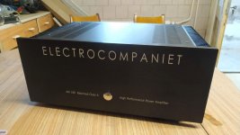
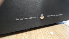
Beautifully made amplifier, looks very professional indeed!
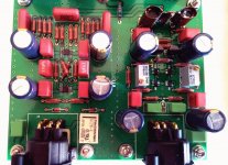
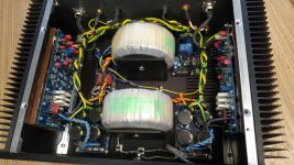
A question. The original AW120 has 5 x parallel .22e resistors in the VCC supply and no emitter resistors. Why did you choose to use emitter resistors?
Personally, I prefer your way, and I see EC do use ER in some (most?) of their other designs.
Did you have difficulty sourcing decent quality output transistors?
Thanks,
Aldo
Beautifully made amplifier, looks very professional indeed!
A question. The original AW120 has 5 x parallel .22e resistors in the VCC supply and no emitter resistors. Why did you choose to use emitter resistors?
Personally, I prefer your way, and I see EC do use ER in some (most?) of their other designs.
Did you have difficulty sourcing decent quality output transistors?
Thanks,
Aldo
Hi Aldo,
sorry I missed your post, only bumped into it just now somehow!
I was not aware that the original AW120 had no emitter resistors. I have seen this approach in older EC designs, such as the AW100, but the AW120 EC schematic that I have seen and circulates freely on the net to EC's distaste employs emitter resistors.
Emitter resistors do help control thermal runaway in bipolar output stages. In multiple paralleled output device configurations they also help in dividing the output current more evenly between devices. It is my understanding that EC has adopted this practice at least over the last 15 years. Wouldn't you say so?
Cheers,
Hollow
sorry I missed your post, only bumped into it just now somehow!
I was not aware that the original AW120 had no emitter resistors. I have seen this approach in older EC designs, such as the AW100, but the AW120 EC schematic that I have seen and circulates freely on the net to EC's distaste
employs emitter resistors.Emitter resistors do help control thermal runaway in bipolar output stages. In multiple paralleled output device configurations they also help in dividing the output current more evenly between devices. It is my understanding that EC has adopted this practice at least over the last 15 years. Wouldn't you say so?
Cheers,
Hollow
Hi Hollow,
It does happen when you post a lot that it becomes difficult to remember when and where and to follow them all
I can confirm that the original AW120 is indeed emitter resistor free. Not only that, in the course of production (of this same model) the pcb was slightly revised and the output devices changed as well - I think the updated board used the 1943/5200 combo (and 1302/3281 on the older). Both revisions are free from emitter resistors.
There was a unit I worked on that had been, according to the customer, problematic from new. Apparently one complete module was changed under warranty. Whether it had two newer or two older modules to begin with, I cannot say for certain. But now it has one of each. Somewhere I have photos of the two revisions.
I have also seen a collection of EC diagrams spread over the net. I strongly suspect that many have been drawn by end users such as you and I; people who have CAD programs and are able to create a professional looking schematic and do board layouts. Certainly, some have been 'condensed' and have mistakes.
And I completely agree about the thermal runaway and the load sharing. Perhaps that explains why this unit was repaired so often? And why EC adopted ER in later designs. Either way, it seems the ER free version can be reliable as long as great care is taken with matching of output devices.
Aldo
Hello Hollow,
You have a a beautiful amp design and built. I can sure see you enjoying it for many years from now. I have a EC AW 2x120 on my bench, it had issues with micro controlled protection board and output transistors too. Thy do not have emitter resistors and the OPT are MJL 21193/21164 from ON semi.
I am facing problem in sourcing original 2sa970 and 2sc2240. Where did you procure your devices? Would be great help if you can share the source the information
Last edited:
Sense signal?
In the original schematic, at the speaker protection part, there is a SenseL and SenseR signal input. Where is this Sense signal coming from, in the main schematic?
That' d be the schematic.
In the original schematic, at the speaker protection part, there is a SenseL and SenseR signal input. Where is this Sense signal coming from, in the main schematic?
- Status
- This old topic is closed. If you want to reopen this topic, contact a moderator using the "Report Post" button.
- Home
- Amplifiers
- Solid State
- New Electrocompaniet AW120 clone