Has anyone tried the NJM2114 as a NE5532 replacement?
Looking at the specs in comparison to a NE5532, there are many improvements in SR(15V/us),BW(13MHz),Noise(0.9uV),OffsetV,drive.
What stuck me is the current noise is a fair bit lower and so is the low frequency voltage noise, so I wonder if it is noticeable in the phono section?
Not that your ears are going to tell a difference, just something to try, everyone likes to roll opamps don't they?")
Looking at the specs in comparison to a NE5532, there are many improvements in SR(15V/us),BW(13MHz),Noise(0.9uV),OffsetV,drive.
What stuck me is the current noise is a fair bit lower and so is the low frequency voltage noise, so I wonder if it is noticeable in the phono section?
Not that your ears are going to tell a difference, just something to try, everyone likes to roll opamps don't they?
Last edited:
Two: I cannot achieve a complete null with the volume pot at minimum. I can still hear the faint sound of the music. In his book "Small Signal Audio Design" he indicates that the noise output of a Baxandall volume control is not zero when the volume is set to minimum. I assume this also applies to a signal source feeding through as well.
No, the effects are quite different. You will not get better than maybe -85 dB offness with an ordinary pot because of the track end-resistance which is still in circuit with the pot fully down.
This is not normally an issue- sounds as if you have rather too much gain in your system. It definiitely is an issue with mixer faders, which need to be really off (-120 dB) so they are of special construction eg the 'infinity off' concept.
Last edited:
I have some schematics from famous audio mixers used world wide in sound studios. Full of 55xx op amps.
Quite so. I seriously doubt if any music produced since 1980 has not been through a 5532, and probably through dozens of them.
We also note that if the op amp has any crossover distortion, its open loop output impedance will be changing as the applied signal current moves the output stage through the crossover region, while will cause the tiny residual signal to be distorted.
Bob
This is not true. The notion of a distorted residual was disposed of by experiment rather than speculation. See p366-368 in Small Signal Audio Design, 2nd edition.
+16dB (across both poles) is a gain of 6.3times.
If you put in a following receiver impedance of 10k (5k on each pole), then you can attenuate the signal by inserting a 2572r reistor in series with each line out and then a 510r shunting the two lines to audio ground.
If this gives a better control of speaker volumes, then you need to find a way to reduce your amplifier gain and/or your preamplifier gain by that excess +16dB.
Rather than adding an attenuator, it would be better to reduce the maximum gain of the volume control. I don't have the diagram with me but the maximum gain is proportional to the shunt feedback resistor(s) of the inverting opamp(s).
Rather than adding an attenuator, it would be better to reduce the maximum gain of the volume control. I don't have the diagram with me but the maximum gain is proportional to the shunt feedback resistor(s) of the inverting opamp(s).
Thanks all for your input.
Following Douglas Self's recommendation to reduce the maximum gain is this correct?
The project called for a 3.3K for the shunt feedback resistor and a 1K for the input resistor. This would give a maximum voltage gain of 3.3 (3.3K/1K=3.3). This translates to a decibel gain of 10.3dB. And I measured 10.4dB on the bench (unbalanced).
I changed the feedback resistor to 2.4K which should give a gain of 2.4 or a decibel gain of 7.3dB. And on the bench my measured gain is in fact 7.3dB (unbalanced).
This helped move the volume knob to a more usable position for my normal listening level.
I am not sure how this affects the low noise design. I suspect that the resistor Johnson noise will be less. An improvement.
This is not true. The notion of a distorted residual was disposed of by experiment rather than speculation. See p366-368 in Small Signal Audio Design, 2nd edition.
Hi Doug,
Not so fast. Most of us, including me, do not have the second edition of your small signal book, and there is no reference to such an experiment in the first edition. Can you please briefly describe the experiment and its results here, so that we can ourselves evaluate whether the "notion" really was disposed of. BTW, theory is not speculation. Did you also confirm your experiment with a proper simulation that includes a reasonably accurate model of the 5532 and its distortion mechanisms?
Bob
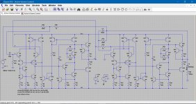
I don't know if this is a help or a hindrance but LTSpice includes a 'real' opamp made from discrete parts in the examples. OK, so its a 741 type but non the less......
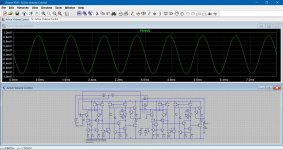
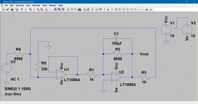
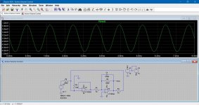
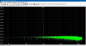
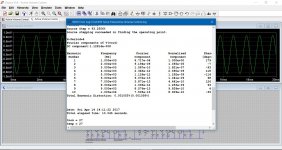
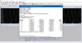
Here are two examples of the active volume control, one using standard opamp models included with LT and one using the discrete opamp. The output stage current of the 741 was set to 1.7 milliamps.
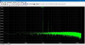
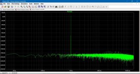
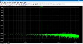
The images show in order the circuit setup, the output voltage and the FFT for both versions. The last two FFT's are with the attenuation factor altered and the 'pot' setting resistor at 2000/8000 ohm.
The distortion results (final two shots) show that the distortion does indeed rise at high attenuation for the discrete opamp... but as to whether this little experiment is useful or not I wouldn't like to say.
Here are two examples of the active volume control, one using standard opamp models included with LT and one using the discrete opamp. The output stage current of the 741 was set to 1.7 milliamps.
The images show in order the circuit setup, the output voltage and the FFT for both versions. The last two FFT's are with the attenuation factor altered and the 'pot' setting resistor at 2000/8000 ohm.
The distortion results (final two shots) show that the distortion does indeed rise at high attenuation for the discrete opamp... but as to whether this little experiment is useful or not I wouldn't like to say.
Attachments
I have seen that for the 5532 op amp expensive 100pF polystyrene capacitors are used (pin 6-7). The argument here is also the less distortion. In my opinion, in this case, however, cheap ceramic capacitors would be sufficient without the distortions increasing.
Last edited:
I have seen that for the 5532 op amp expensive 100pF polystyrene capacitors are used (pin 6-7). The argument here is also the less distortion. In my opinion, in this case, however, cheap ceramic capacitors would be sufficient without the distortions increasing.
I believe that only 33pF external compensation capacitance is necessary to make the 5534 unity gain stable. This should be a COG (NPO) ceramic capacitor. In any application involving a "noise gain" of 3 or more, no compensation capacitance is needed, and higher slew rate and lower HF THD are obtained. Note that the noise gain of a unity-gain inverter is 2, meaning that considerably less than 33pF of external capacitance is required. Further note that an inverting summer of 2 input signals, each with unity gain, has a noise gain of 3, and thus needs no external compensating capacitor.
Cheers,
Bob
I would say 22pF should suffice for a unity gain config, but they are a bit differ from manufacture to manufacture. Also if you are trying to squeeze each mm of GBW, it is possible to use a sort of double pole arrangement on comp pins, or use lag compensation around the opamp.
No, the effects are quite different. You will not get better than maybe -85 dB offness with an ordinary pot because of the track end-resistance which is still in circuit with the pot fully down.
This is not normally an issue- sounds as if you have rather too much gain in your system. It definiitely is an issue with mixer faders, which need to be really off (-120 dB) so they are of special construction eg the 'infinity off' concept.
TI engineer Ian Williams Claims -103dB (measured) offness.
http://www.ti.com/lit/pdf/tidu034
Last edited:
Does anyone know a good distortion-free mute circuit?
Douglas Self's Small Signal Audio Design book discussed muting circuits in Chapter 21 (Signal Switching). Might want to check there.
Hi Guys
If muting si supposed to be 'off' and not a just a specific level reduction, then the relay is the cleanest way to go. It provides muting at startup and power down when controlled the right way; basically the NC contact is used and the relay is powered to open and unshort the output of the preamp. Even though the signal does not actually pass through the contacts when the preamp is in use, it is best to have gold contact and even better if the relay is \sealed with a noble gas inside.
Just looked at the first post of this thread:
9ppm 1kHz at 1V is not great for a preamp these days, but is typical of what you get using ICs. The nominal resolution limit of AP27xx is about 2.5ppm, although with a spectrum analyser you can mine down further. High-end preamps (which do not require exotic circuits or parts, but are usually discrete) have unmeasurable THD20 at normal signal levels.
A relay to short the o/p to ground, but use a minimum 600 ohm source resistor b4 the relay.
Why would you use the mute relay to short an op-amps' OUTput to ground? I usually make mute relays disengage the output and short the INput of the following stage to ground, then you don't need to mess about with another resistor that increases output impedance......
Last edited:
- Home
- Source & Line
- Analog Line Level
- New Doug Self pre-amp design...