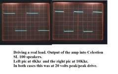

Mooly said:Driving a real speaker at 4 and 10 Khz.
for being such HIGH VOLTAGE output = +- 20 Volt peak
those are close to perfect squarewaves.
There is no overshooting. No ringing.
The square also show that this amplifier is quite FAST.
= good and high bandwidth
(Because we can see a slight rise in upper left corner. Even on the 10 kHz)
Congratulations

Mooly said:As promised a couple more actual shots.
Class AB without feedback by voltage?
Unbelievable!
 Mooly & Wavebourn
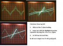
That crossover distortion Shot
and by biasing 200 mA in IRF240 / IRF9240 output stage
remove the same.
Great
And very instructive.This is also very much according to what we know about HEXFET.
They need a bit higher Idle Bias than bjt.
200 mA is a figure I have seen in several other MOSFET AB Power Amplifiers.
Thanks, Mooly.
One of the advantages of HEC is it senses output error and amplifies it inversely, thus creating very good damping, even with the lower transconductance of MOSFET compared to BJT.Mooly said:... What I keep thinking is this. When you hang a large speaker on the end of an amp, it behaves as a generator as well. Each speaker of a stereo pair must behave as a microphone and that signal is forced back into the feedback node of the amp. Is that influencing the sound ? Under transient conditions how well does EC cope.....
G.Kleinschmidt said:Each to their own, but running the output stage out of the loop without class A bias will give you an awfull lot of crossover (nasty high order) distortion with these devices. Full amplitude distortion may be in the vicinity of 0.5-1%, worse with decreasing amplitude.
 Even with higher bias, there will be some crossover components that exist as one transistor switches off and the other turns on. In fig 2 of Bob's paper, it shows that at low current around cutoff, the slope of the curve Vgs vs Id is less until conductance is 1A or so. In class AB, each transistor passes through this transfer region. This is an advantage BJT's have over fets. As Glen pointed out crossover distortion contains high frequency components that the global feedback loop can't really correct for.
 This picture shows the output at 10Vp @ 30KHz across 5 Ohms resistive and the error (1V/div) when the output fets are under bias in class B and have lots of crossover distortion. The slope of the error signal at crossover indicates the very high frequencies needed to correct this enormous error. As fast as the error amplifiers are, they still cannot correct for all of the crossover as it is still visible. (Vgs Th for the fets is 3.8V and here Vgs is 3.2V.) Without the EC the crossover notch would be much more pronounced.
Attachments
That crossover distortion Shot
and by biasing 200 mA in IRF240 / IRF9240 output stage
remove the same.
Great
This is also very much according to what we know about HEXFET.
They need a bit higher Idle Bias than bjt.
200 mA is a figure I have seen in several other MOSFET AB Power Amplifiers.
Thanks, Mooly.
Higher bias is needed for the reason Bob explains in his paper. However, even with bias there will be some bit of crossover that will have to be dealt with via GNF or EC. In this picture, the same conditions exist as above but with 300mA of bias. You can still see a slight variation in the slope of the error signal at crossover. This indicates that even with 300mA of bias you still cannot get rid of it all without correction....or class A bias.

Attachments
Yeah,
your are very right, CBS240
This is one reason why Nelson Pass drives his HEXFET in Class A
or at least at very high idle currents.
Look at his Pass Alephs amplifiers
They simple like more idle currents, those IRF mosfets.
How much is up to you.
The level of feedback used is one important factor.
Will correct crossover distortion a bit.
By using a local feedback loop, the distortion seen by the GNF loop from that stage is much less. It is best to have the global feedback loop "correcting" as little distortion as possible, just like you want each stage of the amplifier to work as little as possible to drive the next stage. Therefore each stage within the loop must be as linear as possible. Relying on the global feedback to correct all ills is the reason why some people criticize fb, unjustly IMHO.

Morning all,
I don't think Wavebourn is very impressed by all this . I wanted to try something different and to see how it sounds.
So the next step has to be a PCB to tidy things up -- which is a good excuse to try some photo sensitive spray I got instead of pre sensitized boards.
Lineup - if you look at the shots driving the speaker there is a slight rise in amplitude at 10Khz caused I think by the impedance of the speaker increasing. The relatively high output resistance of the FET's highlighting the effect. In absolute terms ( in db ) the effect is tiny.
Thanks for the continued interest.
I don't think Wavebourn is very impressed by all this
. I wanted to try something different and to see how it sounds. So the next step has to be a PCB to tidy things up -- which is a good excuse to try some photo sensitive spray I got instead of pre sensitized boards.
Lineup - if you look at the shots driving the speaker there is a slight rise in amplitude at 10Khz caused I think by the impedance of the speaker increasing. The relatively high output resistance of the FET's highlighting the effect. In absolute terms ( in db ) the effect is tiny.
Thanks for the continued interest.
Hi Mooly,
Excellent results, and it shows that sims never show the real picture. Had you used a simulator you may not have tried any of this. I'm a simulator Luddite as well you see ...
I used positive resist spray some years ago. It worked better for me than the negative stuff did. Same for pre-sensitized PCBs. I still have some that I was going to perfect printing a pattern on acetate with. That never did work well.
The best results I found was to spray the boards, then stick them in a box, emulsion up. Dust can be a problem at times. After leaving it sit overnight, you should get them warm in an oven for at least 1/2 hour, but not too hot or it won't work. I used a #2 photo flood about 10" from the board's surface. The thing that was a giant help was to use a pair of muffin fans to cool the board as you exposed it. If you aren't using incandescent photo floods, you may be fine. Extra cooling can't hurt though. I've heard of people using sunlight for exposing the PCB. It never worked for me and I can't imagine you'd have any kind of control over exposure. This trial is what prompted me to sensitize my own boards. Reworks on spoiled test boards.
In the end, using the spray on blank PCBs turn out well. It also allowed me to use different PCB materials, copper weight and substrate thickness. Doing double sided boards was no problem either. I wish I knew how to plate holes through though. I haven't made a photo etched PCB in many years, but I think the chemicals are much the same these days.
Good luck, and I'm pretty sure you'll have success with this.
-Chris
Hi Chris,
Thanks for the kind words. I have the greatest admiration for the guys that use simulators, but I think using one correctly is as much an art as designing "the old fashioned way" sometimes.
I'm the same with programming and PIC's... as I often say "how hard can it be to light an LED up".
I too make very few PCB's these days, but have perfected the technique of using a special film in an ordinary inkjet in conjunction with "Diptrace"... and can say results are absolutely superb. SMD is no problem and the boards are 100% with no pin holes or "strands" etc. I use a small UV lightbox. As I do so few I find it helps to keep notes of exact printer settings and exposure times to refer back too... if your like me, 6 months down the line and you've forgotten what worked best.
This was the last one,
http://www.diyaudio.com/forums/head...-ended-class-headphone-amp-2.html#post2110766
My experiments with spray on resist weren't to successful, consistency being the problem... and my lack of patience. Perhaps I should try again.
I'm lucky in having a large component distributer within fairly easy reach so I can get fresh pre sensitized board as and when needed.
thanks again Chris
Any Updates Mooly?
Afraid not... I never took it to a fully worked and built up design.
- Status
- This old topic is closed. If you want to reopen this topic, contact a moderator using the "Report Post" button.
- Home
- Amplifiers
- Solid State
- New Design-HEXFET Poweramp. Sonic benefits of this approach.