Babowana said:I have changed some of resistor values.
Any good advice? Otherwise, I would just go with this . . .
Seasons Greetings,
")
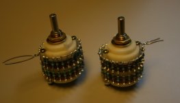
I am collecting materials for a B-1 and scored a 2 pole 24 position Shallcross switch . Unfortunately,it is not make before break. Is it usable without creating problems.?? Or do I have the proverbial "White Elephant".
Seasons Greetings.
sandyhooker said:
... not make before break.
It's useful for the series or ladder type attenuators.
Cheers,
>>
<<
Re: oops
I was aware that the commercial versions of these attenuators are make before brake. What specific problems other than "popping" can occur?? Are there serious electrical considerations?? The switch I have is a beauty ...I would love to use it if possible..
AndrewT said:Thanks Zen.
yes, make before break behaves differently from break before make.
I was aware that the commercial versions of these attenuators are make before brake. What specific problems other than "popping" can occur?? Are there serious electrical considerations?? The switch I have is a beauty ...I would love to use it if possible..
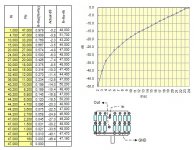
The volume attenuator is a voltage divider having two variable resistors—i.e. the upper, Ri and the lower, Rg. The wiper of the attenuator is the output of the voltage divider. Of course, when we rotate the volume knob, the values of Ri and Rg are changed.
The "not-make-before-brake" means that the wiper of rotary switch can be briefly located in-between the contact points without touching the contact points.
Let's talk about the "series" or "ladder" type attenuator (voltage divider) made with the not-make-before-brake rotary switch. Its wiper of the switch is soldered to the amp's input. So, the amp's input sees the wiper only. And, when the wiper is briefly located in-between the contact points, it is entirely free from any contact so that the amp's input is totally open. I.e., the amp becomes mute. In this case, we don't hear the “pop?in rotating the volume knob.
Meanwhile, when we talk about the "shunt" type volume attenuator, the amp’s input is soldered not only to the wiper, but also directly to the output of the voltage divider. So, when the wiper is briefly located in-between the contact points, the amp have input has to see the full volume. Therefore, when we rotate the volume knob, we briefly hear the peak sounds like “pop?“pop?“pop? We need to use the make-before-brake for the shunt attenuator . . .
I have used the “not-brake-before-brake?for the series and ladder type attenuators without any problem. Used even ugly ones . . .
Seasons Greetings,
>><<
Listening to Joe Cocker Have a Little Faith in Me . . .
The "not-make-before-brake" means that the wiper of rotary switch can be briefly located in-between the contact points without touching the contact points.
Let's talk about the "series" or "ladder" type attenuator (voltage divider) made with the not-make-before-brake rotary switch. Its wiper of the switch is soldered to the amp's input. So, the amp's input sees the wiper only. And, when the wiper is briefly located in-between the contact points, it is entirely free from any contact so that the amp's input is totally open. I.e., the amp becomes mute. In this case, we don't hear the “pop?in rotating the volume knob.
Meanwhile, when we talk about the "shunt" type volume attenuator, the amp’s input is soldered not only to the wiper, but also directly to the output of the voltage divider. So, when the wiper is briefly located in-between the contact points, the amp have input has to see the full volume. Therefore, when we rotate the volume knob, we briefly hear the peak sounds like “pop?“pop?“pop? We need to use the make-before-brake for the shunt attenuator . . .
I have used the “not-brake-before-brake?for the series and ladder type attenuators without any problem. Used even ugly ones . . .
Seasons Greetings,
>>
<<Listening to Joe Cocker
Have a Little Faith in Me . . . in a conventional non-inverting amplifier, if the input is open circuited it can cause the amp to oscillate or the input to act as an antenna. Both of these open circuit conditions can be solved with appropriate circuitry. But one must "design" for this eventuality.
If the inverting amp has an open circuit input what happens to the gain?
Is there a circuit solution to the open circuit problem for inverting topology?
If the inverting amp has an open circuit input what happens to the gain?
Is there a circuit solution to the open circuit problem for inverting topology?
Babowana said:
I have used the “not-brake-before-brake?for the series and ladder type attenuators without any problem. Used even ugly ones . . .
[/i]
As usual ,good news from the Baboman,,,Thanks for the info!
JT
AndrewT said:
... one must "design" for ...
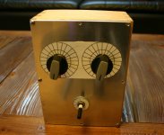
Papa has designed B1, and from tonight, I'm using two mono ladder type 47K attenuators made with "not-make-before brake" 24-step rotary switches at the input of the B1. Great!
Papa is a master designer, isn't he?
Season's Greetings
>>
<<Babowana said:
Papa has designed B1, and from tonight, I'm using two mono ladder type 47K attenuators made with "not-make-before brake" 24-step rotary switches at the input of the B1. Great!
Papa is a master designer, isn't he?
Season's Greetings
>>
YouBetchaBabo

Season's Greetings!!!

Many thanks, Steen.
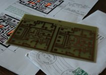
Today, I received the pakage of cute-sized pc board for the shunt regulator, its schmetic and detailed instruction notes Very nice new year gift for me The instruction is so detailed that I could build it even with my blind-eyes 
I will start from the collection of components . . .
Happy New Year to you!

Today, I received the pakage of cute-sized pc board for the shunt regulator, its schmetic and detailed instruction notes
Very nice new year gift for me The instruction is so detailed that I could build it even with my blind-eyes I will start from the collection of components . . .
Happy New Year to you!
Attachments
Before I start any diyaudio project, I like looking at the schematic for a while till I feel self-confidence on it. Just looking . . . In the course of this warming-up weeks, if I feel some modification of it for my purpose, I try to think about a revision darwing.
Attached is a minor revision of the shunt reg received from Steen. I want to change few resistors and the reference voltage as shown. The reason is that I want to get regulated Vout of about 18V from the unregulated Vin of about 30V. Any comment on the new values? Will this work? Thanks.
Cheers,
>><<
Attached is a minor revision of the shunt reg received from Steen. I want to change few resistors and the reference voltage as shown. The reason is that I want to get regulated Vout of about 18V from the unregulated Vin of about 30V. Any comment on the new values? Will this work? Thanks.
Cheers,
>>
<<Attachments
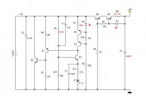
AndrewT said:change R5 & R6 to something sensible.
What do you mean with "something sensible" . . . ???
>>
- Status
- This old topic is closed. If you want to reopen this topic, contact a moderator using the "Report Post" button.
- Home
- Amplifiers
- Pass Labs
- New-building of my B1 buffer