steenoe said:
Hi, Steen
Thanks for the valuable info.
For example, as follows?
Upper Idss - Lower Idss
8.67mA - 8.5mA
8.68mA - 8.5mA
>>
") <<
<< <<
<<
Babowana,
Neat build, did you etch a board? Or, is this a P2P? I couldn't make it out from the picture.
I'd like to DIY my own version of the B-1, I'm trying to decide P2P/make a board.
Is it possible you would have more photos, and willingness to post them??
It would be much appreciated.
John
Neat build, did you etch a board? Or, is this a P2P? I couldn't make it out from the picture.
I'd like to DIY my own version of the B-1, I'm trying to decide P2P/make a board.
Is it possible you would have more photos, and willingness to post them??
It would be much appreciated.
John
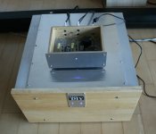
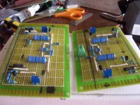
Here is a close-up view of my baby B1.
I made exactly the same PCB as shown in the post #1, but the size was adjusted to a bit smaller dimension, 170mmX120mm, fit for the box.
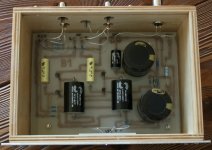
Two fat electrolytic caps are Korean made, Samhwa. One black film cap of 1uF is parallel with one of the two fat caps. Two black film caps of 10uF are output-coupling caps. Two yellow film caps of 1uF are input-coupling caps (Icel of 1% tolerance). I got these film caps from my old diy-projects
All resistors are Korean made, except Panasonic 1-ohm-2W resistor just behind the +19V inlet.
By the way, you might wonder with . . . You see?
The input and output RCA connections have (+) wires only. Where are the (ground) connections?
>><<
I made exactly the same PCB as shown in the post #1, but the size was adjusted to a bit smaller dimension, 170mmX120mm, fit for the box.
Two fat electrolytic caps are Korean made, Samhwa. One black film cap of 1uF is parallel with one of the two fat caps. Two black film caps of 10uF are output-coupling caps. Two yellow film caps of 1uF are input-coupling caps (Icel of 1% tolerance). I got these film caps from my old diy-projects
All resistors are Korean made, except Panasonic 1-ohm-2W resistor just behind the +19V inlet.
By the way, you might wonder with . . . You see?
The input and output RCA connections have (+) wires only. Where are the (ground) connections?
>>
<<Attachments
Babowana said:..... Where are the (ground) connections?
>>
ya have backplate , grounding them all
Zen Mod said:
ya have backplate , grounding them all
>>
 <<
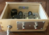
<<Here is back side (or rear side) view . . . which English is correct . . . ?
The aluminium (or aluminum) back plate is a common ground for the all RCA connectors. And, the center of the plate having the same distance to each PCA connector is connected to the GND point of the PCB.
Seasons Greetings,
>>
<<Attachments
Babowana said:
>>
Here is back side (or rear side) view . . . which English is correct . . . ?
Either one is fine.
The aluminium (or aluminum) back plate is a common ground for the all RCA connectors. And, the center of the plate having the same distance to each PCA connector is connected to the GND point of the PCB.
Seasons Greetings,
Very attractive build, Babowana.
eLarson said:
Very attractive build, Babowana.
mightym said:
Very nice looking unit.
Thanks.
Seasons Greetings,
>>
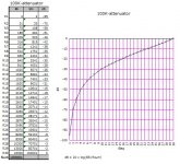
<<moe29 said:What are you using as volume control?
At present, I'm using 100K as shown.
But, I'm thinking of a linear pot of 25K having -40dB to 0dB . . .
Seasons Greetings,
>>
<<Attachments
mightym said:Babowana,
Thank you for the additional photos.
I have researched the PCB method you used, very smart for one-off use, simple, draw the circuit, etch the board.
Very nice looking unit.
John
Some tips from personal experience on this PCB method. Clean the board well ..Do not use a scotch pad or the like but rather use a methylated degreaser ... no fingerprints allowed. I've had fair results with "Sharpies" but better for this are oil based paint markers . I bought UNI-PAINT Markers $2-$3 on line. I also bought a dispenser of liquid flux $7 from Mouser to coat the traces
after etching so that a coat of solder would flow their course. I still use P2P ( I find it relaxing) and will post some Pics of my F5 boards if I can figure out how to post pictures on the forum. I'm envious of the beautiful artwork and resultant boards . Babo's boards are'nt as pretty but they WORK ...in the end that's what this is all about!!
PS. Use new board material rather than old oxidized stuff. Keep it from the air untill you are prepared to use it, clean it and go to work. Good Luck!!
sandyhooker said:Babo's boards are'nt as pretty but they WORK ...in the end that's what this is all about!!
Thanks for the nice words.
I like to do focusing on the heart . . . but if the body could be also pretty, it would be:

One day . . .
Cheers.

Babowana said:
At present, I'm using 100K as shown.
But, I'm thinking of a linear pot of 25K having -40dB to 0dB . . .
Seasons Greetings,
>>
The volume control gets me every time! Looking forward to see
what you come up with : )
I think that B1 is a really really good pre for me to fully enjoy the first watt music together with F5 and with my 85dB speakers (ATC SCM7).
For the time being I'm using 100K 30-step stereo log attenuator (series type) for the volume control.
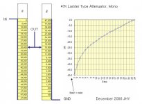
BTW, our living room has asymmetric shape so that the volumes between the left and right speakers are also a bit asymmetric. So, I have to move my music listening positions here and there. This is not very convinient. Mmm . . . I need to consider a new volume control -- e.g. two mono 47K log attenuators (ladder type). And, if I give these to B1, it must be that I could have a possibility of adjusting the left and right volumes independantly at the fixed listening position, then without moving my heavy aass here and there. Is this just a excuse to maintain building of something . . . ?
?
Seasons Greetings,
>><<
For the time being I'm using 100K 30-step stereo log attenuator (series type) for the volume control.
BTW, our living room has asymmetric shape so that the volumes between the left and right speakers are also a bit asymmetric. So, I have to move my music listening positions here and there. This is not very convinient. Mmm . . . I need to consider a new volume control -- e.g. two mono 47K log attenuators (ladder type). And, if I give these to B1, it must be that I could have a possibility of adjusting the left and right volumes independantly at the fixed listening position, then without moving my heavy aass here and there. Is this just a excuse to maintain building of something . . .
?Seasons Greetings,
>>
<<Attachments
- Status
- This old topic is closed. If you want to reopen this topic, contact a moderator using the "Report Post" button.
- Home
- Amplifiers
- Pass Labs
- New-building of my B1 buffer