I'd look at the transient response to address or possibly alleviate concerns about a non-monotonic phase response.
Years ago I chatted with Keith Johnson about settling time, and at that moment he dismissed it as being nearly irrelevant. My supposition was that whereas data acquisition systems only had to wait until a transient has settled to the required error band, in an audio system one was listening all the time, and the nature of the settling transient might be audible.
A while later I was reading some marketing blurb about new Spectral amps, and they were touting the rapid settling time")
Years ago I chatted with Keith Johnson about settling time, and at that moment he dismissed it as being nearly irrelevant. My supposition was that whereas data acquisition systems only had to wait until a transient has settled to the required error band, in an audio system one was listening all the time, and the nature of the settling transient might be audible.
A while later I was reading some marketing blurb about new Spectral amps, and they were touting the rapid settling time
If we build something we are always thrilled that it works and that it does not sound like total crap.
On the contrary, without these roller coaster impossible to build an amplifier with a THD of less than a thousandth of a percent. The sound is excellent, after all the feedback depth is a minimum of 70 dB at 20 kHz and at least 100 dB below range. No useful signal at frequencies in the megahertz, that we use.Overall I like your designs. I just don't understand how such a roller-coaster phase plot can be conducive to good sound or good performance?
I guess that assertion depends a lot on the open-loop linearity. It's not an unreasonable statement, but will surely depend on the details of the topologies.On the contrary, without these roller coaster impossible to build an amplifier with a THD of less than a thousandth of a percent. The sound is excellent, after all the feedback depth is a minimum of 70 dB at 20 kHz and at least 100 dB below range. No useful signal at frequencies in the megahertz, that we use.
As can be gleaned from many sources, the correlation of low distortion with sound quality continues to remain elusive---although I prefer clean. The interminable Sound Quality vs. Measurements thread, which has become the domain of a couple of writers now, still came nowhere near to any sort of agreement among the participants. John Atkinson of Stereophile has expressed his own dissatisfactions as well, in trying to correlate the judgments of his subjective reviewers with his own objective measurements.
Yes, this problem has all the signs of the eternal, and, hopefully, in our lifetime it is not resolved.I guess that assertion depends a lot on the open-loop linearity. It's not an unreasonable statement, but will surely depend on the details of the topologies.
As can be gleaned from many sources, the correlation of low distortion with sound quality continues to remain elusive---although I prefer clean. The interminable Sound Quality vs. Measurements thread, which has become the domain of a couple of writers now, still came nowhere near to any sort of agreement among the participants. John Atkinson of Stereophile has expressed his own dissatisfactions as well, in trying to correlate the judgments of his subjective reviewers with his own objective measurements.
I mean, at a frequency of about 10...20 kHz, all other frequencies such parameters are achieved relatively easily due to the great depth of feedback.On the contrary, without these roller coaster impossible to build an amplifier with a THD of less than a thousandth of a percent.
John Atkinson of Stereophile has expressed his own dissatisfactions as well, in trying to correlate the judgments of his subjective reviewers with his own objective measurements.
Yes, but his problem is on the listening test end (which his "reviewers" don't actually do), not the measurements end (which are done quite capably).
I concur. But there would go the magazine.Yes, but his problem is on the listening test end (which his "reviewers" don't actually do), not the measurements end (which are done quite capably).
It would be nice but probably drive away a good many reviewers to have them take a real hearing test too. One fairly recent review indicated that more than an entire missing upper octave in a product was undetected by the subjective reviewer.
Actually I have a few quibbles with some of his measurement techniques, but he is head and shoulders above the rest of the glossy mags. For example, he has a curious notion that the worst case for evaluating noise is to short the input of a device and set the gain to maximum, which would only be true for a shunt feedback input stage with an input resistor, an unusual case.
He also ignores parallel (i.e. "current") noise in preamps, which we know is quite important for MM phono at high frequencies. But he is in "good" company here, as virtually all manufacturers do the same thing.
And for crosstalk, which is a specification IMO absurdly overvalued most of the time, he attributes the degradation at higher frequencies to capacitative coupling. This is not a methodological issue but an interpretive one, as crosstalk can come equally well from inductive coupling.
Overall though we are fortunate to have him. I still subscribe.
Hi Guys
T117 wrote: "On the contrary, without these roller coaster impossible to build an amplifier with a THD of less than a thousandth of a percent."
In my designs, the sims show a flat phase response and THD20 is a few ppm for the super-power circuits and <1ppm for lower power. THD1 is all-zeroes in LTspice, which is <10ppb, at any sane useful power and less than 1ppm at super-power. I do a few things I've been advised against - always have... haha - and the real world results have been acceptable. THD is below what I can measure.
For my own stereo needs I measured how much power is required for insane loudness and designed the amp to be all-zeroes at any power level I actually use. If the hardware lives up to the simulation I can't say, but it is below what I can measure and sounds better than what I've used so far, so that's good. I will try anything that theoretically reduces the distortion further.
Have fun
Bryston get quite good distortion results for using the garden variety inexpensive parts they use: generic transistors, inexpensive metal film resistors, one pair of fixed voltage 3 terminal regulators feeding all stages and both channels of a preamp or crossovers etc. A Bryston preamp or dac may have 3 to 5 electrolytic coupling caps per channel ( much cheaper than matching input pairs, the time and cost of a trim pot to get rid of offset, servos, or film coupling caps). I find Bryston products to be limited in resolution and tiring to listen to in the long run regardless of their distortion improvements.
Hi Guys
ticknpop: Sounds like you prefer LPs?
Bryston did use 3-terminal regulators until a few years ago, and now use a single BJT + zener regulators since they wanted to increase the voltages slightly from 24V to 30V.
Bryston's basic topologies for their discrete opamps for the preamps and for their power amps has not changed significantly since their inception in the 1970s. The big change came in the PAs with high-voltage complementary BJTs that allowed the implementation of the Quad Complementary output stage in lieu of the cascoded enhanced-CFP. The compensation for the amps confuses most designers, and overall hobbyists looking at schematics only do not see anything "modern" or "interesting" and dismiss the whole thing.
Everyone is entitled to their opinion about sound, but I suspect the weak link(s) in your system were not the Bryston amp. If you are used to coloured sound then a low-THD amp will seem lifeless and boring.
In the title of this thread, the quoted THD is actually quite miserable as 0.001% is 10ppm. That is about 1970s performance.
Have fun
Can you show a diagram or model?In my designs, the sims show a flat phase response and THD20 is a few ppm for the super-power circuits and <1ppm for lower power. THD1 is all-zeroes in LTspice, which is <10ppb, at any sane useful power and less than 1ppm at super-power.
Hi Guys
I do my circuit and PCB design on an offline computer.
The circuits are all fully complementary, with comp diff amps that are resistively loaded and using a resistor-CS instead of active-CSs, followed by an EF-VAS. The VAS Re has a small cap across it, usually 100pF, and a small shunt cap to ground from the collector. Most of the amps use output-inclusive compensation. The small amps I built for home use have a CFP output with a buffer driving them. The front end runs off 24V rails and the output stage uses lower ones since it is biased hot. Two such amps drive the speaker in bridge mode to eliminate ground reference disturbance.
The high-power amps using 100V rails have a double-cascoded input stage - all BCs up to the EF for the EF-VAS,then D-gain-group 2SA1831-2SC3503s for VAS and predrivers. Usually 1302-3281 outputs, sometimes using 4793-1837 as drivers. I've designed these larger amps using a variety of output stages, including EF3, EF4, CFP and Quad-Comp-followers, sometimes with class-G multi-rails.
Class-G or H tends to have miserable THD compared to a straight linear amp, so I use a hybrid circuit that also simplifies the protection. The class-G using an EF4 and eight output pairs sims at about 3ppm20 at 2 and 4R at full output.
In all the amps, the closed-loop phase response follows the shape of the closed-loop gain. In built amps, I bandwidth limit the input and use a choke at the output. None of this is what I would consider noteworthy. My math skills are limited and my knowledge of Nyquist next to zero, so probably I'm doing things the hard way, but keeping things simple so i can understand them.
I believe chasing those extra zeroes is worthwile, at least when it is decreasing distortions... monetary zeroes are another thing...
Have fun
Hi Guys
I do my circuit and PCB design on an offline computer.
Have fun
This is not good enough excuse to show schematic, picture talks many languages, English words only English.
Hi Guys
T117: Nothing to do with Lin or Thompson. More like an evolution of Leech. Fully symmetric - neither Lin nor Thompson are.
The circuit descriptions above are pretty straightforward. Like I said, there is nothing new in them just a lot of tweaking despite the fact that most of the values are also tired but proven. I'll see if I can get a schemo on a USB key sometime.
Have fun
Understand you.More like an evolution of Leech.
Hi Guys
T117: Nothing to do with Lin or Thompson. More like an evolution of Leech. Fully symmetric - neither Lin nor Thompson are.
The circuit descriptions above are pretty straightforward. Like I said, there is nothing new in them just a lot of tweaking despite the fact that most of the values are also tired but proven. I'll see if I can get a schemo on a USB key sometime.
Have fun
I know Leach, but I am interested in your compensation. You said you used multiple compensation with no roller coaster open loop phase behavior.
Hi Guys
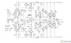
Here are some PDFs of some basic circuits I use. The input section is uncommited with respect to being inverting or noninverting, but that is inconsequential to the compensation shown. I said above that the compensation is usually output-inclusive mixed with some shunt to ground from the VAS outputs - pretty standard as far as I know.
There is also a typical EF3 output section showing the protection method I use. The bias BJT mounts on the face of one of the output devices for quicker response. Yes, there are no base-stops. I've never found a need for them and the output stages I've built never oscillate. Maybe I'm just lucky?
Not shown is the decoupling between the input section and output section.
When you look at old amp designs, the Ampzilla used the EF-VAS but then had other strange amendments no one would do these days. I believe it was those those other things that lead to some of the problems with those amps. What I've done is nothing unusual although not everyone would do it this way.
When I've sim'd Bryston's circuits, the results are not that great, but their actual assembled circuits measure very well. So what is up with the sim? I think there are aspects of the way circuits are analysed that do not tell the whole story, whether it is with respect to THD or stability or whatever else.... so, I choose to believe the parts that make sense to me and verify as much as possible with measurement.
Many people here expect to clip their amps even if they have 100s of watts. I don't. My little amp is "super power" compared to what I need and clips at maybe 8W output. It does not matter though since I never drive it that loud and the clip indicators never come on. So, although I prefer for an amp to clip gracefully, it is not something I worry about too much. I prefer to limit the signal ahead of the amp input as Cordell suggests.
Note that when I referred to "super amps" in the posts above, I was talking about 1kW+.
Have fun
Attachments
Last edited:
- Status
- This old topic is closed. If you want to reopen this topic, contact a moderator using the "Report Post" button.
- Home
- Amplifiers
- Solid State
- New Bryston input stage measurable distortion < 0.001% (Audio Advisor)