I was thinking about a six-transistor output stage from several years ago.Bryston's Quad-Complementary output stage is far from unstable or problematic - I have used it in many amps over the years and it works extremely well with all loads,
Hi Struth, I'm the original poster. I'm the one who carefully typed a direct quote from the sales blurb in Audio Advisor's newest product catalog.If the original poster bothered to trace out the circuit in his "Cubed" amp he would find something quite more typically Bryston and far unlike that in the patent.
The new 4B3 power amplifier -- and all of Bryston's Cubed Series amplifiers -- features a new patented input circuit developed in conjunction with Dr. Alexandru Salomie that is precisely optimized and linear beyond any that Bryston has used before.
It seems to me that Audio Advisor directly states, with no equivocation, the new patented input circuit is in the "4Bcubed" and all other "cubed" Bryston amplifiers.Of course they could simply be wrong. Or confused. Or stretching the truth for the purposes of sales and marketing.
Perhaps there is another patented input circuit developed in conjunction with Dr. Alexandru Salomie, another one besides US 8466744. Perhaps it is this other patented input circuit that is in the 4Bcubed and all other cubed amplifiers. Although I did search hard for all such patents, including both issued patents and patent applications not yet issued, I might have missed one. Or perhaps Dr. Salomie, living in Hawaii USA, applied for and was granted a patent in another country besides the USA. He seems to be from Romania by way of Belgium, those might be possibilities.
I happen to favor the Occam's Razor explanation myself: Audio Advisor is mistaken. Their writing staff, accustomed to hype and half-truths and wild exaggerations, put lipstick on the wrong pig. Nevertheless it IS amusing to compare the sales blurb to the patented circuit itself. Reading what people have to say about it, here in this thread, has been endlessly hilarious.
Mark,
I have gone over the patent you cited. As I read it the claim to fame is using filtering to reduce the distortion. Mostly from the source. They expand the claim to every amplifier topology they can think of.
Now using a filter on the output one might indeed be able to reach the claimed distortion products at one frequency.
They also seem to think they are using CFP circuitry.
So as I read it, the parts you sketched are just one of the possible topologies they are using with the filters.
Now I can see two advantages to including an input filter, one is line noise and the other is EMI particularly artifacts from a signal source from a digital player.
Now as to an input filter being original!!!!
ES
Member
Joined 2009
Paid Member
I used pretty much the same regime in my Lifeforce 100 in 2006. It was very linear and I achieved very low distortion with only 15dB of global feedback.
I'm with the skeptics; it is based on the Sziklai overlay on a LTP, difficult to argue it was not done years ago.
Your Lifeforce was what I based my TGM2 amplifier on. I didn't use a current mirror though. The improvement in clarity and bass impact compared with the same circuit not using a CFP in the LTP (TGM1) was quite astounding.
Or at least the wrong lipstick.I happen to favor the Occam's Razor explanation myself: Audio Advisor is mistaken. Their writing staff, accustomed to hype and half-truths and wild exaggerations, put lipstick on the wrong pig. Nevertheless it IS amusing to compare the sales blurb to the patented circuit itself. Reading what people have to say about it, here in this thread, has been endlessly hilarious.
I have no axe to grind about Bryston. I do find patents like the one in question quite annoying. There have been plenty of them lately, open season on prior art. The one in question here is also evidence of some serious misunderstandings. I must admit that the laundry list of "may be a arcilated thermamatoic LTP" and the ilk is amusing---did we forget anything?
An anecdote from years back: Harman was involved in a movie theater system in southern Calif. and used the "second-label" out of Madrigal for the amplifiers, Proceed I believe it was. One golden-eared person winced in pain when he heard the system, which others had supposed adequate and decent-sounding. The GEP insisted that the amplifiers be changed to Bryston, and when this was done evinced a sigh of relief.
Somewhat more complicated than that.
Hi guys;
I am the person at Bryston who worked with Dr. Salomie, (now sadly passed away), while he was developing the new buffer circuit. First, yes, the diagrams shown in the patent are somewhat simplified and representative. Second, much of what the patent describes has to do with the novel methods of maintaining stability in the circuit, as well as its ability to reject PS and CM noise. Bryston amps are well-known for linearity, focus, depth of field. The new Cubed Series is an evolutionary improvement on all the above, especially in 'difficult' environs. I hope that helps, at least a little.
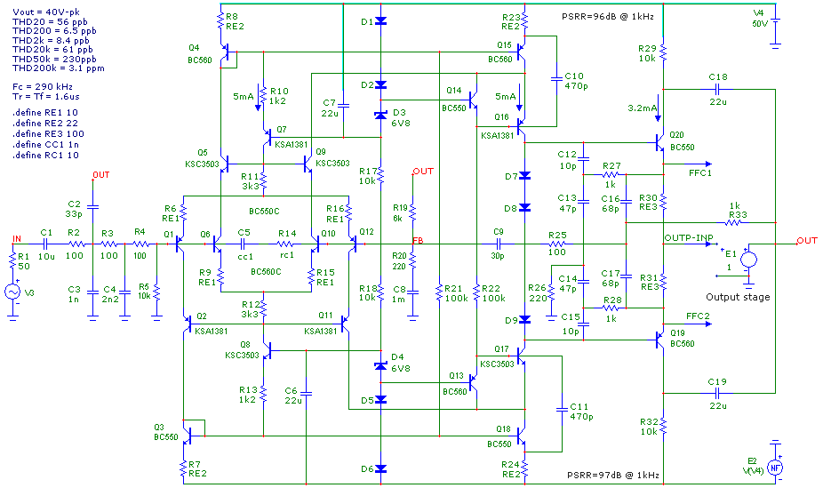
Just received the Audio Advisor catalog SP116 and noticed this blurb on page 5, about the Bryston 4B cubed power ampThe new 4B3 power amplifier -- and all of Bryston's Cubed Series amplifiers -- features a new patented input circuit developed in conjunction with Dr. Alexandru Salomie that is precisely optimized and linear beyond any that Bryston has used before. ... The new input stage is so transparent its measurable distortion is less than 1/1000th of 1 percent!So I visited the US Patent and Trademark Office website and searched for patents that either (a) had Alaxandru Salomie as one of the named inventors; or else (b) was assigned to Bryston. I only found one: US Patent number 8,466,744 (attached below).
It shows an input stage with a two complementary feedback pairs in a differential amplifier, with a current mirror load, and a third CFP used as a second stage, plus cascode. I redrew it below because the figures in the patent are crapped up with shaded overlays.
For this they got a patent?
_
Hi guys;
I am the person at Bryston who worked with Dr. Salomie, (now sadly passed away), while he was developing the new buffer circuit. First, yes, the diagrams shown in the patent are somewhat simplified and representative. Second, much of what the patent describes has to do with the novel methods of maintaining stability in the circuit, as well as its ability to reject PS and CM noise. Bryston amps are well-known for linearity, focus, depth of field. The new Cubed Series is an evolutionary improvement on all the above, especially in 'difficult' environs. I hope that helps, at least a little.
I don't think this is "super pair" or CFP pair. I think that each amplifying device is isolated by emitter follower here.
Maybe so, I guess I was thinking they both can be used as an error corrected follower. In the first case the feedback makes the input high impedance if the device is biased with a current source, though it is true you only have one beta.
Hi Guys
One thing to note about patents for circuits is that values cannot be patented. Many think they can and this is often their motivation to get the patent - that they have found the "magic values" for a given circuit effect. For example, Randall Smith's patent for the power supply filter node of the screens in a tube output stage. He came up with values that to him gave a pleasing sag effect, so applied for one of his many invalid patents.
So, those who look at the Bryston patent and see values given and then try simulating the circuits, you are looking at one possible arrangement for a nonspecified application. How can you interpret the results with so much missing info?
Regarding the "six transistor output stage": That is the one used in the original 2B, which later became the 2B-LP (low profile) and also in later models like the 60W integrated amp. It is basically a CFP with gain with the added current gain of a third stage. Most people who have issue with CFPs with gain illustrate the circuit using only two devices per side. That is entirely ill-conceived except for the purpose of dissaudinbg others from using the circuit. With the added current gain, the loop resistor values can be made higher and more reasonable and the loop is more accurate. Normal compensation is added to the input device of each circuit half, as well as across the series feedback resistors. Again, a stable circuit that works well since the early 1970s.
I admit to being a fan of Bryston and of Chris Russell. When I first became aware of his products back in 1981 and saw schematics of what was being built then, I was struck by the elegance of the designs and the genius of Chris's compensation scheme - no one else uses it. Later when he came up with the Quad-Comp output stage - when devices were finally available to implement such a circuit - it was a stellar leap in circuit development and performance. All the way along, continuous research into reducing distortions and improving performance has meant that each generation of amps is a little bit better than previous ones. The new input circuit filter is just one of those evolutions - there have been input filters right from the start.
Bryston amps tend to show up the flaws in the rest of the audio system, so they won't appeal to everyone. No amp can.
The Audio Advisor quote is accurate inasmuch as the new circuit is applied to all of the "cubed" products.
Have fun
Hi Guys
One thing to note about patents for circuits is that values cannot be patented. Many think they can and this is often their motivation to get the patent - that they have found the "magic values" for a given circuit effect.
Claims that narrow have virtually no value.
I don't see anything revolutionary about the stability compensation used in this amplifier. It is a combination of shunt compensation, miller compensation, and maybe PLIL ("SRC" network across the LTP bases). These are well-known, just not by the DIY community. It seems that feasibilty of a design for DIY is inversely related to the number of poles in the feedback loop, so naturally a lot of designs remain obscure.
From here:
Super TIS
From here:
Super TIS
Hi Guys
In my view, all distortions created by electronic circuits are "unnatural" inasmuch as we did not evolve to compensate for their presence. Sounds in the natural environment are distorted by several means, but most of these result in timbral changes that our brains know how to deal with. Electronic circuits add new harmonics that are either musically related or not, with the latter being especially problematic to the intelligibility of the sound.
With the above in mind, I would suggest that ignoring specifications is foolhardy. There are some distortions that we know of and can measure to an extent. There may be other distortions that are not yet defined or are poorly defined and/or difficult to measure. We can only do what technology allows at any given moment, but we should recognise its offerings and give them the deserved weight.
Our senses can detect things to incredibly tiny levels - parts-per-million easily and parts-per-billion not unreasonably. A THD figure of 0.000 1% represents 1ppm. This is below the resolution of the AP-sys2 but not below our hearing sensitivity. It is the goal of serious audio designers to eliminate distortions to whatever extent their skills allow, which makes the musical experience much more satisfying.
The situation where a high-THD amp is compared to a low-THD amp and a listener prefers the high-THD sound is common. The high-THD amp typically has high levels of musically-related low-order harmonic distortion, which can sound subjectively pleasing with simple music. With dense music, it will sound like mud and one cannot help realise the unit is deficient for true music reproduction. The low-THD amp may have distortion harmonics that go to a higher order, but which are much more fatiguing to our brain, proving the sensitivity we have to miniscule distortions and also demonstrating the unnaturalness of those distortions.
We each choose our audio system elements on an ultimately subjective basis. We are trying to find the system that excites us to listen to music. For me, the system with lowest distortion always wins.
With regard to the complex compensation schemes: Many of those have to me a very odd phase response, at least as simulation software is programmed to display it. Quite often the phase line looks like a roller coaster, and some have postulated that what is key is where the line is at the unity-gain point and how steep it is thereabouts. Intuitively the phase response should be flat within the pass band and that is what I always aim for.
Keentoken: neither of your links work.
Have fun
Hi!With regard to the complex compensation schemes: Many of those have to me a very odd phase response, at least as simulation software is programmed to display it. Quite often the phase line looks like a roller coaster, and some have postulated that what is key is where the line is at the unity-gain point and how steep it is thereabouts. Intuitively the phase response should be flat within the pass band and that is what I always aim for.
I agree with you in everything except for two points.
Fans of large distortions really like large distortion. Maybe it has something to do with childhood memories and the sound which they then heard. They call dirty sound "alive" and "with the soul"
") , and the sound of amplifiers with low distortion - "dead" and "impartial, aloof " , their ideal - the gramophone. It is impossible to look at the electrical schematics of their amps without tears and laughter. What kind of sound they want, evident by the recordings of Glenn Miller: it is unfortunate that there were no modern electronics.
, and the sound of amplifiers with low distortion - "dead" and "impartial, aloof " , their ideal - the gramophone. It is impossible to look at the electrical schematics of their amps without tears and laughter. What kind of sound they want, evident by the recordings of Glenn Miller: it is unfortunate that there were no modern electronics.The depth of feedback depends on the ULGF. Without the compensation according to the Nyquist offset at some frequencies the phase for 180 degrees, to achieve the desired depth of feedback is impossible.
For example here http://www.diyaudio.com/forums/solid-state/290970-several-schemes.html#post4706538 http://www.diyaudio.com/forums/atta...47885d1462713695-several-schemes-donetsk.zip:
Attachments
Hi Guys
T117: I grew up listening to tube amps and LPs and that was my first hand experience with musical systems. There is a nostalgic feeling we all have to recapture the excitement of the first sounds we heard, however, for me that experience evolved with my exposure to better systems. There are many people who never get past that initial experience and crave the added harmonics of tubes and nonoptimal solid-state circuitry and strange speaker setups.
The National Rsearch Council (NRC) of Canada conducted blind tests of listeners and audio systems back in the 1970s or early 80s. Their conclusions were that most people favour the system with the lowest distortion and flattest frequency response., which concurs with my statement above that electronic distortions are unnatural and we seek a musical experience without them.
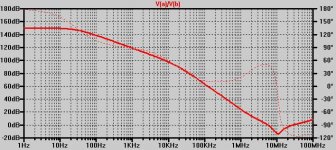
Your thumbnail plot is an open-loop response. I was referring to closed-loop response. I know you've looked at one of Dadod's CFA amps and was not too impressed. His designs always have the roller-coaster closed-loop phase response, and it is only recently that he has got THD figures down to what I consider acceptable. His current-conveyor preamp has a flat phase response, which I believe to be much more suitable, as Marshall Leech described back in 1978.
Fortunately there are lots of things that can sound good to us. If we build something we are always thrilled that it works and that it does not sound like total crap. Once you listen to it for a while you hear the deficiencies, and this is most often revealed with dense music. Open, airy music is always the type the SE mosfet and tube guys listen to, and that music sounds good through practically anything... well, maybe not ipods and suchlike...
In the range of signal levels used by most people, Bryston's preamps have THD unmeasurable by an AP. Their PAs are getting there.
Have fun
T117: I grew up listening to tube amps and LPs and that was my first hand experience with musical systems. There is a nostalgic feeling we all have to recapture the excitement of the first sounds we heard, however, for me that experience evolved with my exposure to better systems. There are many people who never get past that initial experience and crave the added harmonics of tubes and nonoptimal solid-state circuitry and strange speaker setups.
The National Rsearch Council (NRC) of Canada conducted blind tests of listeners and audio systems back in the 1970s or early 80s. Their conclusions were that most people favour the system with the lowest distortion and flattest frequency response., which concurs with my statement above that electronic distortions are unnatural and we seek a musical experience without them.
Your thumbnail plot is an open-loop response. I was referring to closed-loop response. I know you've looked at one of Dadod's CFA amps and was not too impressed. His designs always have the roller-coaster closed-loop phase response, and it is only recently that he has got THD figures down to what I consider acceptable. His current-conveyor preamp has a flat phase response, which I believe to be much more suitable, as Marshall Leech described back in 1978.
Fortunately there are lots of things that can sound good to us. If we build something we are always thrilled that it works and that it does not sound like total crap. Once you listen to it for a while you hear the deficiencies, and this is most often revealed with dense music. Open, airy music is always the type the SE mosfet and tube guys listen to, and that music sounds good through practically anything... well, maybe not ipods and suchlike...
In the range of signal levels used by most people, Bryston's preamps have THD unmeasurable by an AP. Their PAs are getting there.
Have fun
Hi Guys
Your thumbnail plot is an open-loop response. I was referring to closed-loop response. I know you've looked at one of Dadod's CFA amps and was not too impressed. His designs always have the roller-coaster closed-loop phase response, and it is only recently that he has got THD figures down to what I consider acceptable. His current-conveyor preamp has a flat phase response, which I believe to be much more suitable, as Marshall Leech described back in 1978.
Have fun
This VFA is even with lower distortion then my CFA.
http://www.diyaudio.com/forums/solid-state/182554-thermaltrak-tmc-amp-7.html#post2960995
Hi Guys
Dadod: Your link goes to a post near a schematic but no gain/phase plot or THD numbers.
Overall I like your designs. I just don't understand how such a roller-coaster phase plot can be conducive to good sound or good performance?
Have fun
I don't see why you are afraid of that type compensation(two poles). The close loop gain has very nice phase behavior. By the way, the sound is fabulous.
Yes spare textures are favored by the SE crowd. I visited the home of someone late of JBL who specialized in loudspeakers for the Japanese market. I hoped to audition his system with some orchestral material, but out of an entire wall of CDs there was ONE symphonic pops CD, and very few other instrumentals per se. What were all the other CDs?Fortunately there are lots of things that can sound good to us. If we build something we are always thrilled that it works and that it does not sound like total crap. Once you listen to it for a while you hear the deficiencies, and this is most often revealed with dense music. Open, airy music is always the type the SE mosfet and tube guys listen to, and that music sounds good through practically anything... well, maybe not ipods and suchlike...
Female vocals with (afaik) sparse instrumental accompaniment. It all made sense. Actually I think the biamped system used actual push-pull tube amps (Quicksilver iirc) for the mid-highs and a big-a$$ solid state power amp for the woofers. It did play very loud.
And yes, the amp only its mother can love (unless it just sounds awful), a very strong effect indeed.
Hi Guys
Dadod: I'm not afraid of two-pole comp and use output-inclusive comp in my amps. My Q still is unanswered, though. Amps like your CFA s and the other guy's "amp designed during lunch breaks" both have a phase response that is never a straight line and goes up and down and up and down. Both amps have multiple compensation loops.
My amps have multiple compensations means also, but the phase response is flat within the closed-loop bandwidth. This makes sense to me. I'm not doing anything novel as far as I know.
I guess my Q boils down to just waning to understand the importance of phase response. I know about phase margin, rather it is the shape of the phase curve I question.
Have fun
- Status
- This old topic is closed. If you want to reopen this topic, contact a moderator using the "Report Post" button.
- Home
- Amplifiers
- Solid State
- New Bryston input stage measurable distortion < 0.001% (Audio Advisor)