Better schematic to normal, common, standard headphones that cannot hold to much iddle current,
This one smaller iddle, total 640 mA, this way divided into 4 capsules will be safe.
Power also reduced, and current around 150 mA
Sorry, my mistake.... the other one too big to common cheap headphones (cheap and common, but sometimes very good)
Carlos
This one smaller iddle, total 640 mA, this way divided into 4 capsules will be safe.
Power also reduced, and current around 150 mA
Sorry, my mistake.... the other one too big to common cheap headphones (cheap and common, but sometimes very good)
Carlos
Attachments
Carlos -
DC current through the headphone voice coil is a bad idea. It biases the driver off center and reduces the excursion in one direction. It also dissipates unnecessary heat. Better to use a resistor collector load and couple the headphone through a capacitor.
Also, if you want a simple class A driver like that, at least put some resistance in the emitter for bias stability. Otherwise the operating current will depend completely on transistor parameters, and drift badly with temperature.
You rigth, but try it someday.
If you not already donne, try it someday, just to kid with those things, you will be very well impressed.
If current do not put your "speaker" driver too much to front or back, in other words if not reach near limit excursion you will hear an incredible sound. I made it with old Germanium transistor, and it is working till today, some small noise can be heard, but also noise is a part of nature too... when locked inside a compression chamber, or opposite chamber, decompression chamber, will will hear noise, and not because pressure, because without pression, in silence, the brain and ear noise floor appear... silence its hard to be obtained.
My own was made with 150 ohms resistance (not impedance) Senheiser Microfone, a professional material saved from a fire in our biggest televisions station, this one, by itself is wonderfull, and can be used as dinamic microfone too, with a very good sound... a little easy to saturated in low frequencies.... if you breath on it, diafragm moves backwards... but it has 7 plus 7 milimeters compliance...in my own "reference" audio it moves downwards something about a half... goes down 3 or four milimeters and you do not fell heat touching it minutes after powered.
This is the best (not related energy passing througth it, i now your worries are correct) way to couple, this is the completely direct couple, no transformer, no condenser, and no crossover distortion, may have some different excursions from out to down movements really, but tried it someday.
I also use heavy amplifiers, because i like vibrations in body, feel in the skin and hairs, and sometimes i use this one.
When use this one, i think manking is going wrong way, creating complicated, heavy and worst things. Normally, usually, all the times comparing, no doubts, it beat the best equipments i have heard together speakers.
The best i heard was 1972 Macintosh, a Valve one, not 72 model, older than that, have you seen already something alike shock absorbers used in speaker diafragm, adjustable mini mechanical system?.... i saw it once, was this Macintosh. Maybe this one beat this simple stage.
Not a matter to discuss too much, i think, beeing easy, good to tried.
But i will not dennied the danger you told, off course energy flowing into driver is no good idea.
My unit have less power, and less energy passing, because 150 ohms capsules, i made those, first very dangerous and i told people, depends of the headphone capacity to receive power, and second less dangerous , made this way because the headphones easy to find now a days, cheep and good chinese ones, that can used to test and if damage, a very small money loose, and a very good sound heard.
regards, and thanks your attention and care.
Carlos
Carlos
You can also substitute Headphone with a resistor
You can put a resistor in the colector, with a resistance value lower than the resistance of the headphone voice coil, this way, naturally, more energy will pass througth the resistor and less energy will pass througth the headphone coil, this way, less DC power, less AC power in the headphone.
Also can use a big electrolitc condenser, at least 10000uF, to guarantee very low frequency passes to a low impedance charge... with a lot of over capacitance to guarantee. Audio will loose with a condenser, but still very good.
try it!, you will be surprised and will start to think in a different way...more flexible related power.
Carlos
This one was the best i have made.
There are many good one..... i think even better ones...but i did not made them..so, i cannot say nothing about other headphone amplifier's qualities.
There are people that only introduce a big emitter resistor, into normall power amplifiers and use it as headphone amplifier...others use only the drivers with big emitter resistors removing the output transistors.
Others (zillions of millions) put a resistor in series in the output of some amplifier and this turns the headphone output.
I cannot say too much about those "zilions".... but i think that if one transistor can make the work..why to use many and finally goes reducing the power in the output....those things do not make too much sense to me.
This one i made... and i can say it sounds great....and this is because one single transistor distort less than many.
Simple things normally sounds great... the opposite is when we create distortions and we go correcting here or there...we first create the mess, and them we go cleaning the house.....
I prefer the simple...reason why JLH old designs are great and many sophisticated amplifiers are hard to listen.
regards,
Carlos
Hey there uncle Carlos...
I was just looking for something like this for my wife's little shuffle... it has realy nice sound, but it is a little weak power wise...
I have some questions, as I am still rotten when it comes to using transistors... (just fine with IC's though).
Is the connection on the top left the input, and the bottem left the output? (schematic 1)
Could I run 2 of those off a 9V battery?
How would you say it compares to something like an opa134 or other nice opamp for headphone use?
Carlos, DC (even at this level) through headphones will damage many headphones permanently - I really would not publish such a schematic in good conscience. Also, the operating point of the transistor is very undefined, so is the gain. Best ever sound is not good enough if it works only when the stars align a certain way, and the temperature and pressure are just right, AND it eventually melts your headphones.
this amp is got to be the world's best umm soem of its
unique features nonpolirised input c also bypassed by
low c for high definition beautifulyy smoothed supply etc
seriously headphone amps like this are rare creatures the
thought behind them is tremendous what can i say
i give it 10 out of ten
john
unique features nonpolirised input c also bypassed by
low c for high definition beautifulyy smoothed supply etc
seriously headphone amps like this are rare creatures the
thought behind them is tremendous what can i say
i give it 10 out of ten
john
Hey C, been studying the stuff a little more.
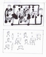
Ok I see the PCB is for 2 channels, and the voltage depends on the transistor I choose... i.e. 35 or 39. (I will go with the first because its more suitable for small transportable amp - needs only 9v)
Why is there only one 10000uf cap on the pcb though?
Doesn't each channel have one?
Will this circuit work well with 16ohm impedance earphones?
Would you mind identifying the pads I marked...?
Attachments
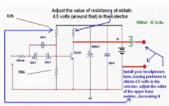
390 ohms is in series with the signal source...one extreme is the input to connect to
audio source.
Well...install your headphones after one electrolitic condenser.... the biggest you can find in your part box...low voltage and hi capacitance..... 1000 uf or much more.
Adjust the colector resistor till you find around 4.5 volts in the transistor colector.
This will protect the headphone, as you will avoid the DC that is turning friends concerned.
I use this amplifier with hi resistance headphones...DC was not a problem there...but of course, each case is a case, and different transistors can create a lot of current there.
Using batteries you will limit your maximum current...and adjusting the colector resistor things will be under control.
The circuit is very basic...super hiper simple, but of course need some experience to measure VBE and conclude if the VBE is adequate or not, also will be needed to check the colector voltage to see if it is around half the supply voltage...well...those basic things are needed, and basic alike not to touch the soldering iron point (this is to Zagreb)
regards,
Carlos
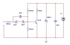
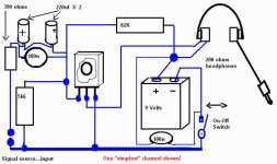
Nordic, this one is special for you...use 220 ohms from positive to colector
You may find something strange with this circuit...was constructed first
time in the sixties…. And sounded great!...many times better than all i
could listen those days…and I think also in our days this circuit may be
unbeatable.
The current that will cross the colector load is around 10 miliamps, and
this is represents a very small power that will not burn, will not overdrive
or damage a 200 ohms impedance (or more) headphone cartridges.
It used, in the past…a Senheiser headphone cartridge that was something
alike the microphone cartridge…and good I have used as microphone cartridge
too…talking on it and pluging it into amplifiers.
With this impedance you will have around 4.5 volts in the colector…45 miliwatts
of power will be wasted in class A current, that will be modulated with the input
audio producing high quality audio.
The circuit is biased in class AB…with around 10 miliamps to colector and
100 times less in the voltage divider that you have in the base….. calculated with 100
microamperes….. the down resistor will keep around 600 milivolts over it
and the upper resistor will take care of the resting 8.4 volts.
The supply is a battery, and the current is around 50 miliamps maximum to
normal carbon cells (not rechargeable)…this is the protection…if you drain too much,
because biasing errors..the voltage will go down….. so…protection enter…hehe
To avoid DC into the headphone’s coils, try the electrolitic condenser in series..use
a good one…a black gate or something very special…as the circuit deserves attention
I made modification in the resistor…the biasing resistors are very strange…and I made
another arrangement….and I will test both of them in this next week.
The BD139 can work with 1 ampere…it will work fine…the gain is around 100…. And some of them can have 130 of gain…this will need a change in the colector resistor, that is fixed in 220 ohms to 100 gain transistors…maybe 180 ohms will work better with
higher gain units.
If someone has something to contribute…to correct, to make it better, respecting the
basic idea, that was something that turn my “nephew” happy…please…go ahead, as
big Uncle Charlie wants nephew happy.
Yes, it will work with 18 ohms headphones and speakers too…. But with the headphone
coil in series with the current…connected between colector and positive supply, the sound is great!
It was made to 200 or more ohms of headphone impedance…and is simple..sounds
simply perfect if correctly biased….600 milivolts or sligthly more from base to emitter,
and something around 4.5 volts DC from colector to ground (negative)
Regards,
Carlos
Attachments
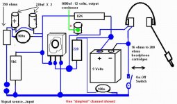
This circuit is modified to block the DC using a condenser.
The quality is worst....really worst...but even worst, is better than many others...thousand of others more complicated.
There's no secret into the simplicity...have only to check if VBE is around 0.6V..... also to check if Colector voltage is set from 3 to 7 Volts DC...prefered is 4.5 volts.
Power consumption is around 10 miliamps in stand by mode.
Power wasted is 45 miliwatts into the colector resistor...also wasted inside the headphone coils.
The output will depend from the signal in the input...but will be nice...more than needed to a headphone cartridge...and many times more than a conventional standard MP3 player...those use 1.5 volts as supply..those thin AAA rechargeable cells.
regards,
Carlos
Attachments
- Status
- This old topic is closed. If you want to reopen this topic, contact a moderator using the "Report Post" button.
- Home
- Amplifiers
- Headphone Systems
- New best wide world headphone amplifier