I promise to build one tommorrow.. must just go and buy a few of the resistor values and the 2 transistors... already got some nice sprague 220uf caps (donated by Franz Gysi), I guess 10V would be enough there?
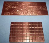
I attached a matrix board layout for one channel?
Would you please check if I got it mostly right... I just used the picture of a regulator instead of the proper transistor, but marked the pin numbers.
I attached a matrix board layout for one channel?
Would you please check if I got it mostly right... I just used the picture of a regulator instead of the proper transistor, but marked the pin numbers.
Attachments
10mA*220Ohms=2.2v
10mA*2.2v=22mW
10*Log10(22mW)=-16.5dB
at 98dB/mW that's around 111.5dB.
Even if it doesn't damage headphones (which it will over time), there will be an enormous turn on pop, reduced excursion capability and greatly increased even order distortion in the headphones themselves.
That along with the other problems with this circuit previously mentioned forces me to recommend that no one build this. Much less use good headphones with it.
Oh dear God!...the Canadien smashed my amplifier..ahahahaha!
In the reality....i made it in the real world and i forgot the the input resistors have to drain 10 times the needed base to emitter current....yeah!..old fellow i am...doing foolishes.
Well...i have lost the beach i will show you...but i made the damned one...and worked fine...i have asked the amplifier about those distortions the Canadien told...the amplifier told me nothing and continued to sound nice.
In a matter of fact..sounded so good as the portable player used to drive...and i had more bass....and the pop turning on..ahahahha!
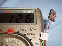
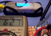
The current gone to 12.8 miliamps after some "adjustment"
The upper base resistor was changed by a 10K ohms
The lower base resistor was changed by a 1100 ohms....1K plus 100 ohms resistor
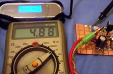
The VBe voltage gone to around 620 milivolts.
The Colector voltage to around 4.98 volts
And sounded great...can be used, and it was used with 16 ohms output..... the output was colected after an electrolitic condenser...not the real wonderfull sound we have when we install things in series with the colector...having current going in...yeah...sounds good!.... of course the current drives a little the diafragm....the speaker, the headphone cartridge...moves a little...but you continue to have room to move upwards and downards.
It is DIY....real world construction..without the need to produce a contest quality, and i had not the intention to make better than Professional....this is DIY....not Professional show room.
Oh Pain...i lost this beach...oh pain!
regards.
Carlos
In the reality....i made it in the real world and i forgot the the input resistors have to drain 10 times the needed base to emitter current....yeah!..old fellow i am...doing foolishes.
Well...i have lost the beach i will show you...but i made the damned one...and worked fine...i have asked the amplifier about those distortions the Canadien told...the amplifier told me nothing and continued to sound nice.
In a matter of fact..sounded so good as the portable player used to drive...and i had more bass....and the pop turning on..ahahahha!
The current gone to 12.8 miliamps after some "adjustment"
The upper base resistor was changed by a 10K ohms
The lower base resistor was changed by a 1100 ohms....1K plus 100 ohms resistor
The VBe voltage gone to around 620 milivolts.
The Colector voltage to around 4.98 volts
And sounded great...can be used, and it was used with 16 ohms output..... the output was colected after an electrolitic condenser...not the real wonderfull sound we have when we install things in series with the colector...having current going in...yeah...sounds good!.... of course the current drives a little the diafragm....the speaker, the headphone cartridge...moves a little...but you continue to have room to move upwards and downards.
It is DIY....real world construction..without the need to produce a contest quality, and i had not the intention to make better than Professional....this is DIY....not Professional show room.
Oh Pain...i lost this beach...oh pain!
regards.
Carlos
Attachments

Hi Uvodee...pics...yeah!...more pictures will be posted here
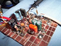
This is the circuit constructed...guaranteed, using Gain BD139 transistors with 130 of gain.
This one was tested...it works!
Nordic...my dear Nephew...please, use this circuit corrected (adjusted to real world...hehe)
regards,
Carlos
This is the circuit constructed...guaranteed, using Gain BD139 transistors with 130 of gain.
This one was tested...it works!
Nordic...my dear Nephew...please, use this circuit corrected (adjusted to real world...hehe)
regards,
Carlos
Attachments
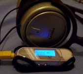
This headphone sounded good..the Sony one did not sounded good.
The problem i had with the Sony one was the very small driver inside....could not reproduce deep bass...and having deep bass going to it, turns distorted.
The Philips one did not distorted.
My beautifull Senheiser is not here...my friend Paulinho is using it, as he loves to Sing popular musics in his home.
No!...negative!.... with the output condenser, nor the sonic qualities nor the power could be compared with the same idea using headphones in series...the perfect coupling...nothing between them....
regards,
Carlos
regards,
Carlos
Attachments


No...you do not have too much power...small resistors will fit.
Nordic...my complete adress is:
Carlos Eugênio Mergulhão
Rua Dona Balbina Menelau 56 - 1601
Candeias - Jaboatão dos Guararapes
Pernambuco - Brasil
54440-331
South America.
I am here...a little bit at south of Recife.
regards,
Carlos
Nordic...my complete adress is:
Carlos Eugênio Mergulhão
Rua Dona Balbina Menelau 56 - 1601
Candeias - Jaboatão dos Guararapes
Pernambuco - Brasil
54440-331
South America.
I am here...a little bit at south of Recife.
regards,
Carlos
Attachments

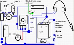
Nordic, your headphone impedance informed was very low.
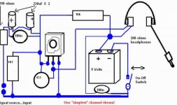
So, do not install it in series with the colector...use a big (1000uf) electrolitic condenser, and fix the colector resistor with 220 ohms.
In the future, if you have a headphone with 200 ohms impedance..then, install the headphone coils in series with the colector..in the place or the 220 ohms resistor....and the electrolitic condenser will not be needed too.
Use, please, this schematic that was tested...observe that it has a capacitor (Ceramic or Silver Mica) from Colector to Base.
regards,
Carlos
Attachments

Well...i am thank you all by your presence
The first diagram is very strange....i was searching the old sketch i have made to check those values.
Reason why two friends are scandalized with it.
Thank you Mylar
Boxedin...i think it will work fine with your Grado...use the last
version…I do not know if your Grado is sensitive, the circuit I am
suggesting you has not a big power to drive non sensitive cartridges.
Ilimzn….i do not think the last version will melt cartridges.
Tim X…. the low impedance is a need…this circuit is adequated to
received pre amplified, low impedance signal sources…as MP3 players
Johndiy…thank you by the nice words…positive things are always good
Uvodee…nice face…nice family…. Thanks to her, because you are happy!
Tim X…thank you to smash my amplifier..this forced me to construct to keep
dark clouds distant
Nordic, dear Nephew!...i hope it is good enougth to you.
Regards,
Carlos.
- Status
- This old topic is closed. If you want to reopen this topic, contact a moderator using the "Report Post" button.
- Home
- Amplifiers
- Headphone Systems
- New best wide world headphone amplifier