Sadly my digital camera died long ago from takeing too many pictures around my fishtanks (rust).
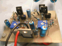
I just made a PCB for the circuit with some bd135s, just used a sharpie marker on the pcb lol. This one is using cheap components... lol the oscon caps on the first protoptype are like twice the thickness of these, not to mention the giant paper caps. (So I needed a new model which was more suitable to go in the small case i have...)
This one looks like it will fit, have space for 3 batteries and the output and powersupply caps which I left offboard...beacause they are even bigger than the other components.
Just makeing some holes in the case to fit the sockets etc should be ready in an hour or so.
Yes..really photo cameras dies easier than tropical fishes diving into cold water
Good to see that you are having fun with this simple circuit.
nice....pitty that you do not have a web camera....that one could help too.
Here is a WEB Cam image.
regards,
Carlos
Good to see that you are having fun with this simple circuit.
nice....pitty that you do not have a web camera....that one could help too.
Here is a WEB Cam image.
regards,
Carlos
Attachments
aaah I didn't know you can do closeups with a webcam these days... they are not too expensive...
Ok , all done, except I must still make a hole for the power slide switch... this one handles much better at 9V (bd135), but the noise floor is much higher... the background noise on the other one was much less... will swap the transisters later on to see if its just the cheap ceramics and electros that I slapped on the little PCB... its tiny, maybe 1inch by 1 and a half.
Also I'm listening to the PC right now, so I don't know if the noise comes from the PC... it sounds like a 50Hz PSU noise if you know what I mean... but its hard to hear when music plays.
I think the output current is more suitable on this transistor as the headphones aren't being killed by the bass.... (does it have less gain?)
Right now the devil is telling me to solder another battery clip in there and see if it doesn't work better with 2, the ones I have are reasonably run down allready.
Ok, my ipod, I mean wife, is home....
So I can do some testing before changeing anything.
It is definatly better suited to the stock ipod earphone... driving considerably more bass than without the amp, but not distoring as much due to overpowering the earphones.
The 50Hz sound is gone, so I was right to assume it comes from the pc... I wouldn't say it is as quiet as the first one I built with the better quality components.. I will build that one into a bigger case with a well filtered mains supply for use around the house.
Going to study your other post relating to the hot amp now. As long as I learn something I don't even care if there is another product out there that is better.
DO you think those resitor values are optimal, or can you think of anything else that could cause the noisefloor.
Oh wait, I swapped earhpones while typeing, ow listeing to my big set, and it sounds nice and laidback in a sexy way, I think the little ipod phones may be too sensitive... posibly a highpass filter could try to keep the output more inline with the headsets actual abilities to produce low frequencies (which I know is not an issue on decent earphones or rather headsets).
Those resistors are optimal to gain 130...but not optimal to different gains
To different gains, the up resistor need to be connected directly to the colector and recalculated.
Noise floor is different now..... very interesting....may be the famous transistor noise...interesting that you are listening it...maybe from the source, because i think the circuit, by itself, will not generate too much noise, as it is a single transistor and current is very low.
But maybe you are discovering something that will be interesting to me to know..... this BD135 sounded less powerfull and with more noise...interesting Nordic.
Continue to send your observations when making changes.
Have you checked the voltages from Base to ground and from colector to ground?
Observe please, Nordic, the change related the value or the colector resistor (the load) and the new connection made with it.
This will turn the circuit less problematic if you replace transistors with other gains than 130
regards,
Carlos
Attachments
Carlos, I'm speaking under correction as I allready closed the case and gave it to my wife... will open it again tommorrow... but I think where other circuit measured close to 5V this one was about 3.5V.
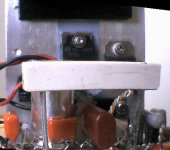
I used a small white pvc case added two 3.5mm sockets, a green power LED and a black slider switch.
I would be lieing if I say there is 0 distortion... I would say the sound is 95%+ pure... but, there is very little distortion when using regular headphones.
The noise floor is also not realy a problem, I thought it was very bad at first when I used the PC as a sound source...but its just the crappy soundcard. I have had a warfedale mp3 player with more noise.
My wife and I both like the headphone amp, I'll try a few other circuits now for comparison as and when I get time.
My conclusion was that the bd135 was more suitable for driving small earphones... the 139 was too powerfull. I have very slight noise on the bd135, still, but its only audiable during silence.
Oh and the fact that the 135 copes with only one 9v battery makes it more suitable...
I wanted to test some more headphone amps today, but an internet domain I was reponsible for got hijacked... and I'm totaly being eaten up by stress today.
Oh and the fact that the 135 copes with only one 9v battery makes it more suitable...
I wanted to test some more headphone amps today, but an internet domain I was reponsible for got hijacked... and I'm totaly being eaten up by stress today.
Hi there uncle Charlie.
I just finished a cmoy headphone amp and dropped the opa2134 from my phonoamp in there...
omw... I think we need to work on the transistor circuit a little...
The BB chip is like driving a hummer through the dessert, the transistor is more like a fiat. I will admit the transistor has a warmer sound, but it is symply not as hi fidelity - a lot cheaper though. It was great fun and gave me more confidence to try transistor circuits. this is the 3rd amp in 3 days I built, you can see its been a few months since I did electronics... I have a hunger for it.
features of opa2134
l ULTRA LOW DISTORTION: 0.00008%
l LOW NOISE: 8nV/ÖHz
l TRUE FET-INPUT: IB = 5pA
l HIGH SPEED:
SLEW RATE: 20V/ms
BANDWIDTH: 8MHz
l HIGH OPEN-LOOP GAIN: 120dB (600W)
l WIDE SUPPLY RANGE: ±2.5V to ±18V

destroyer X said:Grumpf!....Grrrrrr!...better?.....i hate chips
In special when they sounded better than the things i do.
ahahahahahah!
never mind.
and be happy.
Carlos
O, man . . . i don't worry . . . i be happy . . .
No problems guys..some of them are very good...those chips
But there's no "romance"...and without romance life is a sheet... a sheet of papper filled with problems and bills to pay.
hehe.
Those chips, despite nice, are black boxes.... when sometimes you do not know what is inside...no possibilities to make changes...you buy the thing already done...no connections to make, no internal capacitors to choice...well...we only install input, output and supply......hummmmm....not good enougth.
No burned fingers, no mess, nor the feeling that you did something by yourself..... well...in the reality i turn myself "green" of envy when i see people that is satisfied with those spider things....as i cannot feel nothing good related those chips.
The damn OP smashed my poor schematic...but i wanna see, when some internal transistor burns....who will fix it!>
Yes Babowana...be happy....Banzai!!!
ahahahahah!
regards,
Carlos
Attachments

Re: No problems guys..some of them are very good...those chips
i agree at 200% . . .
no fun . . . no life . . .
no man . . . no cry . . .
be happy with our own fun!
destroyer X said:Those chips, despite nice, are black boxes.... when sometimes you do not know what is inside...no possibilities to make changes...you buy the thing already done...no connections to make, no internal capacitors to choice...well...we only install input, output and supply......hummmmm....not good enougth.
ahahahahah!
i agree at 200% . . .
no fun . . . no life . . .
no man . . . no cry . . .
be happy with our own fun!
I believe with the right attitude buildign any circuit can be rewarding... Personaly I go into a mad scientist mode, just grab a piece of PCB and some boxes with components and try to lay the circuits out as small as I can.
I found building the transistor circuit alot of fun, in fact I built 2 prototypes using both transistors.... Its just that I would be lieing to myself if I said the solid state circuits sounded better when all pros and cons were tallied.
I mean in all honesty its a very basic headphone amp desing not accommodating crossfeed etc. Even the C-moy doesn't have it...
Which is why I'm now working on the 4th prototype... based on Rod Elliot's P105 ... you know, just testing, enjoying and haveing fun...
I'm just learning and have no loyalties, whatever I can make sound the best with my current level of skill and knowledge, is exactly what I do... but I will keep on trying your transistors...
That's fine...i like your behavior...and your words make a lot of sense.
Join the crazy scientists group!
Do you use also to give a shot, a double barreled gun...12 gauge shot into the boards when too much frustrated?
Never did that?
hehe...you may try...wonderfull!...Boooooom!
But do not loose time shotting something that is inside watter...the pellets will desintegrated and the board will be there laughing to you..hehe
regards,
Carlos
Attachments

I made plenty of booms!!!! since I started in Sept... nothing big enough to permanently discourage me....
Lol, no I don't take the hammer to stuff... just roll another bit of happyness and light up - I do SOOOOOOO enjoy disasembling dissapointing circuits...not rich enough to just smash perfectly good parts, they can't help it if the circuit sucks now can they?
Lol, no I don't take the hammer to stuff... just roll another bit of happyness and light up
- I do SOOOOOOO enjoy disasembling dissapointing circuits...not rich enough to just smash perfectly good parts, they can't help it if the circuit sucks now can they?
destroyer X said:Better schematic to normal, common, standard headphones that cannot hold to much iddle current,
This one smaller iddle, total 640 mA, this way divided into 4 capsules will be safe.
Power also reduced, and current around 150 mA
Carlos
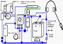
Here is my first HeadPhone amp, built some years ago.
It was used with Sony Fontopia ear plugs (low impedance)
small but with an excellent sound = extra bass.
Details of my first HeadPhones Amp:
- 12 VDC onboard one LM317 regulator
- Two channels on one card share LM317 supply
- Properly decoupled near each channel circuit.
Each channel:
- Two BC550 differential input, resistor set bias in this long tailed pair
- BD140 second stage, with 2 resistor divider set gain
- feedback taken from this stage
- BD139 output voltage follower
- 3 x 1/4 watt metalfilm resistors bias output to ~80 mA idle current
- Input and output uses Capicitors
- Each channel has got a potentiometer,
- for adjust of output working point (originally set at ~9 Volt across 108 Ohm)
I will post some pictures!
With short description.
lineup
- Status
- This old topic is closed. If you want to reopen this topic, contact a moderator using the "Report Post" button.
- Home
- Amplifiers
- Headphone Systems
- New best wide world headphone amplifier