Albrerta,
1. 2x25V AC is a little high for normal operation, where the DC voltage will be about +-34V DC, but if you want to use at high output power levels, considering the voltage drop, there will be about 30-32 V DC on each rail. anyway need to make sure that the possible voltage rise on the mains will not bring this voltages to even higher values where the overvoltage may trip, or even damage the IC if the voltage is over the IC absolute maximum ratings.
2. the preamplifier supply output voltage depends on the value of the components, the resistors from the resistor divider. for +-12V DC the output current can be 250mA.
3. the modules which i have are assembled, but on request, i can sell also the pc alone, or the pcb with parts.
New products were added. One of them, the version v3a of the TA3020 amplifier: http://connexelectronic.com/product...ducts_id/97?osCsid=5u81s5892dspm9g8m0fvpk6ac6
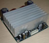
probably the smallest complete TA3020 amplifier which exist. measuring just 100x100x40 mm, is very compact and suitable to use where the space is a real challange.
more details soon.
probably the smallest complete TA3020 amplifier which exist. measuring just 100x100x40 mm, is very compact and suitable to use where the space is a real challange.
more details soon.
Attachments
New products were added. One of them, the version v3a of the TA3020 amplifier: http://connexelectronic.com/product...ducts_id/97?osCsid=5u81s5892dspm9g8m0fvpk6ac6
probably the smallest complete TA3020 amplifier which exist. measuring just 100x100x40 mm, is very compact and suitable to use where the space is a real challange.
more details soon.
probably the smallest complete TA3020 amplifier which exist. measuring just 100x100x40 mm, is very compact and suitable to use where the space is a real challange.
more details soon.
Speaker Protection Circuit is for 2 channels, can be used withstereo amplifiers. can use 10-15V AC power supply or 12-15V DC supply. in case that higher voltage is available only, the resistor R4 connected in series with the relay must be recalculated and C2 must be replaced with a higher voltage one. i can do this on request, when you order the board, if you specify the available voltage.
What is the smallest size transformer that can be used to power the speaker protection circuit, how much current is required?
Also, I noticed that you have added a soft start to your line up. What are the specs and what is required to power that? Will it use the Amplifier PSU or a separate transformer?
Another good addition to your products would be an optical volume control. Maybe something like the "lightspeed attenuator".
col.
New documents added for products !!!
http://connexelectronic.com/index.php/cPath/25?osCsid=ugij1j3tpchnekf8l3mbqidsi1
http://connexelectronic.com/index.php/cPath/25?osCsid=ugij1j3tpchnekf8l3mbqidsi1
there are few minor differences. on V3a i removed the rectifier bridge, the supply for fan, which was on v2, and i changed the SMPS regulators IC. the sound compared with v2 is similar.
note that due to the smaller size of the board and especially the heatsink, it requires a fan to be able to play high output levels. i can add this on request.
the ideea to shrink this board was to make a very compact and easy to install amplifier module, especially for multi-channel amplifiers, where 2-3-4 modules can be used together.
TA2022 and speaker protection circuit
Hi,
I have a few questions about the TA2022 V2. I've tried to understand how to connect everything, and my conclusions are the following :
- PCB's upper side facing me, with the power and speaker connectors on the left, pin number one for input connector is the one on the top
- pins 1 and 2 can be used to power an external LED with a 2K resistor in series
- pins 3 to 6 are for inputs. Clear enough for these
- pins 7 to 9 are for muting purpose : mute when 7 and 8 connected together, unmute when 7 and 9 connected
=> can you correct if I'm wrong ?
Also, do you have an answer for col's question about the speaker protection circuit ? "What is the smallest size transformer that can be used to power the speaker protection circuit, how much current is required?"
Many thanks,
Romain.
Re: TA2022 and speaker protection circuit
Romain,
you are correct, but i will repeat with few explanations.
pin 1 is output for Mute status, as you said can be used to power an external LED or can be used to monitor the amplifier operation by another stages (if you have MCU controller for example)
pin 3, 6, inputs
pin 7 Mute in. a logic level 0 is required for opperation, and logic level 1 (5V) is required fir mute. this levels can be provided y connecting this pin to the apropriate voltage value pins which are on the same connector (pin9 for 0V and pin8 for 5V).
for the speaker protection circuit, the minimum transformer which can be used need to provide at least 9V AC, which after rectifier and filter will be 12V DC. the required current is 50mA, so the transformer power can be less than 1W.
if different voltage value is available, for example 16V AC, this can be also used, but need to change the resistor R4 with different value which need to be recalculated dependin on the board DC voltage and relay DC resistance (ussualy 270 Ohms). if the voltage is higher than 16V AC, the C2 capacitor need to be canged with a hgher voltage one.
the board also can be used with DC power supply, just connect negative voltage to the pin GND, positive voltage to the pin +Vcc and AC1 for AC detect.
romtom said:
- pins 1 and 2 can be used to power an external LED with a 2K resistor in series
- pins 3 to 6 are for inputs. Clear enough for these
- pins 7 to 9 are for muting purpose : mute when 7 and 8 connected together, unmute when 7 and 9 connected
Also, do you have an answer for col's question about the speaker protection circuit ? "What is the smallest size transformer that can be used to power the speaker protection circuit, how much current is required?"
Romain,
you are correct, but i will repeat with few explanations.
pin 1 is output for Mute status, as you said can be used to power an external LED or can be used to monitor the amplifier operation by another stages (if you have MCU controller for example)
pin 3, 6, inputs
pin 7 Mute in. a logic level 0 is required for opperation, and logic level 1 (5V) is required fir mute. this levels can be provided y connecting this pin to the apropriate voltage value pins which are on the same connector (pin9 for 0V and pin8 for 5V).
for the speaker protection circuit, the minimum transformer which can be used need to provide at least 9V AC, which after rectifier and filter will be 12V DC. the required current is 50mA, so the transformer power can be less than 1W.
if different voltage value is available, for example 16V AC, this can be also used, but need to change the resistor R4 with different value which need to be recalculated dependin on the board DC voltage and relay DC resistance (ussualy 270 Ohms). if the voltage is higher than 16V AC, the C2 capacitor need to be canged with a hgher voltage one.
the board also can be used with DC power supply, just connect negative voltage to the pin GND, positive voltage to the pin +Vcc and AC1 for AC detect.
Hi wimpos
this modules have built in supply, the rectifier bridge and capacitors, only need the mains transformer which can provide symmetric AC voltage, 2x20V AC. i can provide you the transformers as well, but they are heavy and the shipping cost may be expensive for them.
an alternative will be to use the SMPS, i pass to production few models, including for this amplifier, and i'm waiting for them next weeks.
pls contact me on pm for more details. also, if you can provide more details about the aplication where you want to use them, we can find the best fit solution.
Hi CNX
thx for the quick reply
I cannot send PM's yet, I am a new member.
I want to make a multiroom system, with an amplifier per room.
This is a proof of concept, so I want to start with your cheapest amps.
Input devices will be line out of pc/tuner/ipod/...
Can you post me a link where I can see some info on symmetric power supplies?
Thanks
Wim
cnx said:an alternative will be to use the SMPS, i pass to production few models, including for this amplifier, and i'm waiting for them next weeks.
Hi cnx,
Considering the price and size of a 200VA transformer, I might be interested in your SMPS supply ;-)
Can you forward me the information about the models you plan to produce, specialy for the TDA8920 modules ?
Romain.
- Status
- Not open for further replies.
- Home
- Vendor's Bazaar
- NEW Audio amplifier kits, modules and many others.