It sounds like the perfect power supply would be the redrock SMPS:
http://www.redrocksaudio.es/files/SMPS6060PFC.pdf
a friend of mine recently bought one of these for a amp project and he requested the voltages he wanted when he ordered it. They are very helpful and the price is very good.
col.
http://www.redrocksaudio.es/files/SMPS6060PFC.pdf
a friend of mine recently bought one of these for a amp project and he requested the voltages he wanted when he ordered it. They are very helpful and the price is very good.
col.
TA2022 questions.
Hi,
I have a few questions regarding your TA2022;
- It does not have any mouting holes, is there any traces near the corners ? It is hard to see from the picture and I do not want to damage anything.
- Is the female part of the white connector supplied.
- Can you supply an appropriate heatsink for this amp, cost please.
- What are the role of the 2 trim pot, is this to fix possible DC offset.
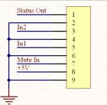
- Is there a wiring diagram available, I wonder why you have a 9 pin connector.
Last, I see a voltage regulator; Is this for the +5Vdc requirements that takes it directly from +30Vdc ?
Many Thanks,
Eric
Hi,
I have a few questions regarding your TA2022;
- It does not have any mouting holes, is there any traces near the corners ? It is hard to see from the picture and I do not want to damage anything.
- Is the female part of the white connector supplied.
- Can you supply an appropriate heatsink for this amp, cost please.
- What are the role of the 2 trim pot, is this to fix possible DC offset.
- Is there a wiring diagram available, I wonder why you have a 9 pin connector.
Last, I see a voltage regulator; Is this for the +5Vdc requirements that takes it directly from +30Vdc ?
Many Thanks,
Eric
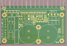
Although i finished the stock of this board, i will give few explanations for who is still interested. The board i will replace with a newer version, which has the rectifier bridge on board, filter capacitors and heatsik. i wait the pcb's from factory, this days should arrive, so in about one week i will have few pcs complete assembled and tested. i will attach some screen-shoot from pcb view.
About TA2022 board, i made this design to fit with a particulat housing, which was also the heatsink for this amplifier. the pcb was kept in place by some side rails in the chassis.
i supply the board with both male-female connector. although i didn't made the photo for heatsink, for those who request i supplied heatsink without additional cost. the trimpot are used to adjust DC offset. the offset is already set, no need to readjust. i will post the pinout for the board, there can see the connections. there are 9 connections because 4 pins are used for GND, 3 for signal in, one mute, one status and one +5V Out. 5V regulator is used to regulate the 5V voltage, from 30V thru one resistor, so on the pins of the regulator are about 20V.
Attachments
cnx, would it be possible to power DA-1 from a pair of 400W 36V SMPS in series? Something like a bigger version of these: http://cgi.ebay.com.au/ws/eBayISAPI.dll?ViewItem&item=190270775068&_trksid=p2759.l1259
A pair wired in series would give me around 800W 72V 20A. Might be a cheap option. I would only have to do the 12V+ separately.
col.
A pair wired in series would give me around 800W 72V 20A. Might be a cheap option. I would only have to do the 12V+ separately.
col.
TA3020 TA2022 DA-1 arrived
Hi Cnx,
My boards just arrived. That was very quick considering the Christmas season.
They are all in good shape and look like they travelled well. One thing, on the TA3020 you need to tighten the signal connection screws before shipping. They had vibrated loose and one of them had fallen out. Luckily I found it in the bottom of the box, it is tiny.
All the boards look very professionally assembled.
Did you see my other questions regarding power supply for the DA-1? Perhaps you are working on a SMPS?
cheers,
col.
TA2022 PCB out of stock or not...
Hi Cristi,
Col just received his boards but I was under the impression that you did not have any TA2022 left, this is why I did not ordered mine. Maybe I will wait for the improved version with bridge rectifier and filtering cap.
Can I order soon or are you still testing the first batch.
Thanks in advance.
Eric
for the TA2022 board, left connector is for power, pin1 +, pin 2,3 GND, pin 4 - . the right connector is for audio output, pin 1 out L pin 2,3 GND, pin 4 Out R. the new TA2022 boards are on the way, i hope will arrive today, i'll let you know when they are here.
untill then, MERRY CHRISTMAS for everybody
untill then, MERRY CHRISTMAS for everybody
Just finished testing new version of TA2022 amp. can be found on this link:http://connexelectronic.com/product...ducts_id=45&osCsid=deqp4aecosab7cncvg2bn7qj31
for any questions, please ask me, and also before placing an order please contact me to get the shipping cost, since the software calculator doesn't always give the correct values. i try to fix this problem, and i also think to use some advanced solution, any advice will be welcome.
for any questions, please ask me, and also before placing an order please contact me to get the shipping cost, since the software calculator doesn't always give the correct values. i try to fix this problem, and i also think to use some advanced solution, any advice will be welcome.
e_fortier said:Hi Martin,
For your second a third questions just look at the available spec sheet
Eric
Thanks for the tip Eric, but I don't see a link to the spec sheet on the Connex website. Do you have a link?
very interesting Amps
Hallo,
i am following this here with great interest.
I am considering buying 2 Stereo Amps for my 2-Way System.
That way i could activate every single channel seperately.
If I decided the TA3020 was the one, which PSU would be the right one. I am not an expert, but I think Power Supply 6x10000uF 80V would match. What kind of toroidal transformer is needed?
Could anybody help me please. Thank you and a happy new year!")
Hallo,
i am following this here with great interest.
I am considering buying 2 Stereo Amps for my 2-Way System.

That way i could activate every single channel seperately.
If I decided the TA3020 was the one, which PSU would be the right one. I am not an expert, but I think Power Supply 6x10000uF 80V would match. What kind of toroidal transformer is needed?
Could anybody help me please. Thank you and a happy new year!
as you assumed, PS10K80 (6x10000uF 80V) would be a good match for TA3020 amplifier. the psu board has 3x10mF capacitors for each rail, in total 6 pcs. 10mF at 80 V capacitors. on request the board can be equipped with even larger capacitors, 15 or 18mF each, giving huge energy reserve.
for the transformer, the power i suggest to be at least the amplifier power, which is maximum 300W per channel, at 4 ohms, voltage depending on the desired output power. for maximum power, need to supply the amplifier with +- 60V, which is about 43.5 V AC at minimum 7A. the transformer should have 2 identical windings, each with this voltage and current rating.
Happy New Year !!!
HAPPY NEW YEAR and ALL THE BEST WISHES !!!
Since few peoples asked me about the modules wheater or not they are assembled or kits, i need to mention that all of them are complete assembled and tested, user, doesn't have to solder any part on them. most of them contains SMD components which requires some skils and can be a chalange for some peoples, especially if they don't have the proper equipment to work with. also, by providing them assembled and tested, the user's can avoid some problems which can lead to components failure if some components were soldered wrong or overheated. also after completion every module is not powerd on directely at nominal voltage, i use a regulated variable supply which have also current limit, set to minimum. in this way if something went wrong in the assembly process can be discovered without smoke and fireworks. after everything is tested, i apply the nominal voltage, and i make the burn-in test, with loudspeakers and power resistors loads. i also test at maximum voltage +5-10% at the limit of overvoltage shut-down.
if some of you preffer to assembly the modules by yourself, i can provide the package with components and pcb separately, and you can enjoy the DIY assembly.
Hello
This is my first post here-
happy new year for all
Few days ago I have received LM4702 SAP15 from Connexelectronic!
Amplifier board looks cool, but there was nothing with, like manuals, schematics,...
On your web site are some datas, but , for example , I dont know, where is + and where is - voltage from supply?
I could track this on board, but this part is not so cool!
Probably lack of papers was caused by christmas das.
Where can I download this documents?
Thanks,
Robert
- Status
- Not open for further replies.
- Home
- Vendor's Bazaar
- NEW Audio amplifier kits, modules and many others.