schematics are nice..... the Fet i tried into the input (alike Roender)
and into the output, as VAS and drivers i have never used.
Yes.... graphics shows nice result, but you may have the same into TGM1 amplifier.... this is a hell difficult to understand.... you may have very different amplifiers in sonics, and measurements almost the same....reason why i do not bother too much with them...i see they tell us that "everthing gonna be all rigth"..but cannot give you the sonics.
Only building... there's no other way.... and comparing..because we use to fool ourselves too.. when non defective, say, not damaged, wrong assembled..we use to love all we do...and this because all amplifiers sounds reasonable..differences are, but very small, and depends on the personal taste, music style, speakers, room acoustic and our own mood...but when we compare we fast see the one plays better together our speaker.
Of course..this does not guarantee it will play that way with other speaker....it is a long search.....very long search..but we have fun doing that.
regards,
Carlos
Gareth,
Your txt/asc trick worked perfectly for me..... I had no trouble opening the circuits briefly with LTSpice, but have been overtaken by events and have not yet examined the non-switch function.
The VAS can simply be buffered with an EF. This confers very strong drive with Zout less than a few ohms, and makes the stage a voltage rather than a current source. In this way wild variations in output stage input impedance are mere bagatelle, and this reduces the errors before feedback.
Carlos, you do me proud. I am sorry that I'm so close with my ideas, but this is a public forum, I work in a competitive environment, and I have no choice. But I'm always willing to discuss privately if you keep things private.
Keantoken makes the good point that non-switching output stages don't much seem to improve the distortion profile in his simulations. I've noticed this too. The vast majority of distortion in output stages seems to be large signal compression, which makes a spray of odd order harmonics, worsening with high amplitude. All the error correction I've examined in simulation doesn't seem to much reduce this distortion either, which is strange, because I can get a buffer to lose less than300mVp rom input to output at 45Vp. From this I conclude that the best EC system is probably very complicated indeed, for marginal subjective gain.
The Self EFII seems about the best to me, good sounding, stable, lots of drive, tolerant of difficult loads. Low emitter resistors seem to help, but this means quiescent hikes up, and matching and bias stability is tricky. But it's very hard to beat an EFII. The diamond buffer is worth experimenting with too, I need to build and listen to one, I'm done with simulating, it's inconclusive. Even a diamond buffer creates a string of odd order artefacts which goes on for MHz, yet it reportedly sounds good.
I wish there were an easy correlation between good sound and THD20. There are lots of strange things happening here.....
Hugh
Yeah.... a double-edged sword dear Hugh
It is pleasant to have some electronics conversation with you, as you are plenty of good ideas, and use to have them first...and then, reserve to you as private things, intelectual property..because your business i understand that.... BUT...has the other side of the same coin.
You know....i love to share... only me listening?..only me using?...this is terrible!... awfull!.. obtaining ideas from you i result myself blocked, as i cannot share.... i have to think all time long:
- "this idea i can use, is it something i can publish?... share? ... and this other one?"
Usually, more often, the answer to myself question is NOT!... i cannot!, because not my idea..belongs to Hugh.
When you have an idea, dear Hugh, as usual, in advance related me and others...if we go NOT knowing your idea... then we can have the same idea and use it, even having that same idea monthes after you had that one... and we can even use it in public if we want.... because not knowing your brainstorms, we avoid your intelectual property... so...the knowledge or your discoveries supresses our freedom.... bad to you... intelectually loneliness may be the consequence to you in the long run.
When you tell us, and ask secret, we gonna be blocked!
Not a very good idea..not entirelly good to go chating with you privately... also, doing that..chating with you, we see how bad we are to have ideas, comparing to your multiple insights!.... if we are not too much idiots, or if we have not all that big EGO..then we realise we are loosers comparing to you..this results strange feelings of love and hate (they live together in perfect harmony)
Cut both sides.... double edged sword....nice conversation, but tie our fingers not to use the keyboard, and tie our tongue not to talk...because of YOUR intelectual property.
I could see, watching your developments those last years...no one can have more ideas and faster than you have.
Sorry...the english seems confused and poor..ideas, ideas, ideas...a lot of the same word, used over and over... i have small dictionaire.
regards,
Carlos
Why don't you take a look at this page I just stumbled across?
Looks very interesting... Also click "home" and browse through his other amplifier ideas. There is some neat stuff here.
http://www.angelfire.com/ab3/mjramp/classb.html
- keantoken
Looks very interesting... Also click "home" and browse through his other amplifier ideas. There is some neat stuff here.
http://www.angelfire.com/ab3/mjramp/classb.html
- keantoken
Member
Joined 2009
Paid Member
Member
Joined 2009
Paid Member
SuperA CFP amplifier...
How about if the real benefit of the non-switching structure is to allow the use of a CFP output ?
Some of the problems with CFP are associated with instability (worse when the devices switch on-off) and control of the cross-over region. They work better in Class A which the non-switching output facilitates.
As Hugh points out, some of the higher order harmonics are due to non-linearity at high output power levels (compression etc.) which is a symmetric distortion in a complementary AB output stage and so produces odd order (nasty) harmonics. But CFP tends to linearize the output so this should benefit. The anticipated reduction in odd order harmonics may be why some people attribute good listening qualities to CFP outputs.
So I put together a crude CFP output with non-switching drive.
We may not believe the sims but it's fun to look now and again...
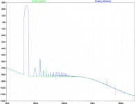
I drove the simulated amp close to full power, which means +/- 1600mV on the input.
Starting without CFP in the output stage, looking at FFTs run at 10kHz (similar trends at 1, 5 and 15kHz)
The attached shows the baseline (blue colour) amp with no SuperA biassing, showing a spray of harmonics from the 7th onwards. Introducing the SuperA biassing to keep the devices always-on is the green trace. The spray of harmonics is greatly reduced (some troubling 5H appears) but not eliminated.
Seems to confirm some benefit in pricinple, from the SuperA biassing that I hadn't uncovered with my initial rough sims.
How about if the real benefit of the non-switching structure is to allow the use of a CFP output ?
Some of the problems with CFP are associated with instability (worse when the devices switch on-off) and control of the cross-over region. They work better in Class A which the non-switching output facilitates.
As Hugh points out, some of the higher order harmonics are due to non-linearity at high output power levels (compression etc.) which is a symmetric distortion in a complementary AB output stage and so produces odd order (nasty) harmonics. But CFP tends to linearize the output so this should benefit. The anticipated reduction in odd order harmonics may be why some people attribute good listening qualities to CFP outputs.
So I put together a crude CFP output with non-switching drive.
We may not believe the sims but it's fun to look now and again...
I drove the simulated amp close to full power, which means +/- 1600mV on the input.
Starting without CFP in the output stage, looking at FFTs run at 10kHz (similar trends at 1, 5 and 15kHz)
The attached shows the baseline (blue colour) amp with no SuperA biassing, showing a spray of harmonics from the 7th onwards. Introducing the SuperA biassing to keep the devices always-on is the green trace. The spray of harmonics is greatly reduced (some troubling 5H appears) but not eliminated.
Seems to confirm some benefit in pricinple, from the SuperA biassing that I hadn't uncovered with my initial rough sims.
Attachments
Member
Joined 2009
Paid Member
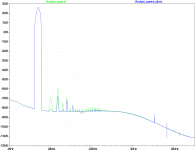
The attached shows the benefit of adding the CFP into the output. The green trace is the superA biassing only, the blue trace with superA and CFP output devices. Even harmonics are pulled way down and the higher order harmonics are almost into the noise floor.
Chalk one up for CFP output in a non-switching configuration.
Chalk one up for CFP output in a non-switching configuration.
Attachments
Member
Joined 2009
Paid Member
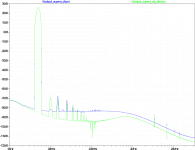
Last improvement is adding the EF bugger to the VAS, pulling the noise floor down. The key is not to wrap Cdom around the whole VAS, just put it on the 2nd device so that Cdom is actively driven from both ends instead of from the LTP output.
Attachments
Member
Joined 2009
Paid Member
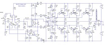
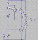
And schematic...
As I understand, the benefit of what I have used for the VAS is in buffering the input stage from the VAS/Cdom (rather than buffering the VAS from the drivers)
"bipolar transistors lose their input impedance as they are increased in operating current and require a constant bias drive because of their finite beta. This can put a significant load on the input stage, without further buffering." - John Curl
Attachments
Hi Bigun,
That technics technique works and is very simple, I use it in several car amps, the results when simulated are not so great as when you actually do a real measurement on a real amp and it affects mostly the high frquencies. Audible it is, but only when I push the amp near its limits and because of this its useful to me as car amps are used for loudness DB competions sometimes. I use another non switching circuit based upon a russian designers work, much more complex, to get excellent THD results but the fact of the matter is that at normal powers these schemes are only good for THD figures and ego as I cannot distinguish a audible difference except when amp is pushed to limits.
That technics technique works and is very simple, I use it in several car amps, the results when simulated are not so great as when you actually do a real measurement on a real amp and it affects mostly the high frquencies. Audible it is, but only when I push the amp near its limits and because of this its useful to me as car amps are used for loudness DB competions sometimes. I use another non switching circuit based upon a russian designers work, much more complex, to get excellent THD results but the fact of the matter is that at normal powers these schemes are only good for THD figures and ego as I cannot distinguish a audible difference except when amp is pushed to limits.
Bigun said:And schematic...
As I understand, the benefit of what I have used for the VAS is in buffering the input stage from the VAS/Cdom (rather than buffering the VAS from the drivers)
"bipolar transistors lose their input impedance as they are increased in operating current and require a constant bias drive because of their finite beta. This can put a significant load on the input stage, without further buffering." - John Curl
I have some input...
Don't use the "npn" model for the VAS transistor - in fact, don't use that model EVER, in a prototype schematic. This models a perfect transistor and therefore deserves a level of respect...
Switch this in for a suitable transistor model. I recommend you use the MPSA18, cascoded (that's what I would do, at least), but it may not be able to drive your OPS.
Next thing, the collector of Q70 is being wasted... Try attaching it to the top of the Vbe multiplier, like in the 5532 schematic:
http://www.dself.dsl.pipex.com/ampins/webbop/5532.htm
- keantoken
Member
Joined 2009
Paid Member
Thanks Homemodder, it's always very useful to get some real world feedback on these things. The technics method adds complexity so you'd want a good reason to use it. I don't plan to use my amps at their limits so perhaps it doesn't offer enough. Still, I find it interesting to explore ideas via simulations - I couldn't possibly build everything that looks interesting. I think OStripper is planning to look at non-switching with MOSFETs at high power levels so it will be interesting to see what method he chooses.
Keantoken, thanks for the input. I do need to update my sims with some proper models, for example, I use the BD139 in my existing VAS.
But I'm not sure why I want to connect the 1st VAS collector to the bias chain ? are you thinking that it might benefit from the VAS bootstrap ?
Keantoken, thanks for the input. I do need to update my sims with some proper models, for example, I use the BD139 in my existing VAS.
But I'm not sure why I want to connect the 1st VAS collector to the bias chain ? are you thinking that it might benefit from the VAS bootstrap ?
Just thought of something else.
Look at the bootstrap reference - the point of a bootstrap is to capacitively couple two points in such a way that there is a constant voltage across a resistor.
So, what we want to do is reference our bootstrap from the place that has negligible drive, but the least voltage fluctuation relative to the top of the Vbe multiplier.
Now the drive to the OPS will always have higher swing than its output, which makes referencing the bootstrap to the output inherently not optimal. This is also prone to injecting odd harmonics into the output, because this is the principle harmonic of a complimentary output stage.
I suggest that you look at which points in the output stage have the lowest voltage fluctuation relative to the top of the Vbe multiplier. Bootstrapping with these points will give you the most constant current. I recommend referencing the bootstrap off of the top of R13. This should inject principally even harmonics.
- keantoken
Member
Joined 2009
Paid Member
keantoken said:Just thought of something else.
[...] I recommend referencing the bootstrap off of the top of R13. This should inject principally even harmonics.- keantoken
In my sims this doesn't help, yes you get more H2 but you get overall higher distortion peaks after H2 also including higher H3. Are you sure we aren't simply loading the poor driver stage assymmetrially and producing lots of H2, H4 etc. ?
Member
Joined 2009
Paid Member
Let me know what you see - it would be better to explore it on something without all the complications I have in my current schematic. It might be worth playing with the values of the resistors that form the potential divider where the bootstrap capacitor joins the VAS power supply - it will have some affect on the harmonics you find.
And schematic...
As I understand, the benefit of what I have used for the VAS is in buffering the input stage from the VAS/Cdom (rather than buffering the VAS from the drivers)
"bipolar transistors lose their input impedance as they are increased in operating current and require a constant bias drive because of their finite beta. This can put a significant load on the input stage, without further buffering." - John Curl
Hi Bigun.
here are my 2 C's...
Looking at your schematic there are 2 "Cdom" capacitors, C8 and C53, that seems to be in the wrong place.
C8, because it is connected to the very low impedance node of Q70 emitter it will have nearly no effect in linearising the VAS stage.
C53, because it's connected to the collector of Q70, but as we are not taking out any signal here we have nothing to win here either.
Remove these 2 capacitors and add one capacitor from collector of VAS transistor to base of Q70.
R147 on the collector side of Q70 is kind of a waste, it also provides a voltage signal out of phase counteracting the base input signal via the non-linear Miller capacitor inside the transistor and will make the stage more non-linear, remove it and connect collector to GND or make a resistor divider from GND to negative rails voltage and add one larger capacitor connected from collector to negative rails voltage.
Good luck!
")
Cheers Michael
Actually, I think C53 has a positive affect.
The voltage at the beginning of the OPS is nonlinear. When we use a Cdom cap as you describe, this nonlinear voltage injects nasty harmonics into the VAS input, when all we were trying to do in the first place was introduce linear HF compensation. The voltage at Q70's collector will still be nonlinear, but it will be 2nd harmonic in nature and won't inject so many HF harmonics into the feedback loop.
To optimize C53, it's best that the highest tolerable value be chosen for R147, as this resistor increases the effectiveness of C53. If this resistor is increased, C53 can be decreased, which will improve THD and LTP operation at HF.
- keantoken
- Status
- This old topic is closed. If you want to reopen this topic, contact a moderator using the "Report Post" button.
- Home
- Amplifiers
- Solid State
- new amp... HARRY 77