Member
Joined 2009
Paid Member
Bigun said:I'm afraid I'm turning into one of those creatures.
I tried to warn you...
To be honest, I haven't been following this, just having a look now and then. The prospect of actually deliberately adding distortion is certainly a different approach.
I have thought about a non-switching output before but I didn't pursue it. When I saw your schematic, I thought that the arrangement just added bias - I couldn't see how it would "slide".
Member
Joined 2009
Paid Member
Originally posted by MJL21193 I tried to warn you...
You did, that's true. I think the antidote is a break. I'm off to a friends cottage for a day this weekend, no computers, no soldering iron. It will be tough...but I will try to console myself with some amber nectar
I've seen the benefits of ClassA now, a dangerous slippery slope perhaps.
Bigun said:
You did, that's true. I think the antidote is a break. I'm off to a friends cottage for a day this weekend, no computers, no soldering iron. It will be tough...but I will try to console myself with some amber nectar
Sounds like fun. I will be working
But the evenings are mine.
I'm a total addict myself - check out what's going on here with my cell phone now and then at work
I limit myself to looking, not posting though so I know my limits!
Member
Joined 2009
Paid Member
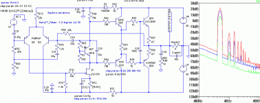
Harry77 with Fetzer VAS
I decided that I needed to showcase my guitar amp credentials for this amplifier so I buried a Fetzer Valve into the VAS.
The schematic is attached. It shows a JFET working as the VAS. This device has a non-linear transfer curve and is set up to produce distortion. The Fetzer Valve is not my inventions, but it's usually employed as a pre-amp.
As the input signal increases the level of distortion rises. Here you see three FFT curves with progressively increasing input signal.
Get those guitars ready
p.s. no Cdom required.
Attachments
Member
Joined 2009
Paid Member
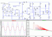
As promised, I have looked at the Wavebourn output structure, one that provides a built-in soft-clipping function.
It works as advertised. I grafted it onto the back of TGM2 to explore this. There's no global negative feedback. The schematic is attached along with output at 3 levels of input and the corresponding FFT. Unfortunately, in my configuration distortion is a bit too high at the low signal levels.
It works as advertised. I grafted it onto the back of TGM2 to explore this. There's no global negative feedback. The schematic is attached along with output at 3 levels of input and the corresponding FFT. Unfortunately, in my configuration distortion is a bit too high at the low signal levels.
Attachments
Member
Joined 2009
Paid Member
CAN YOU HELP ME ?
I'm very curious about the non-switching classB and I have made a simulation based on one of the commercial methods. I can't remember if it's Technics, Sansui or somebody else and it's called something like SuperA or AA or A+. Anyhow, I have the simulation working, I see some clear evidence that the output devices do not turn off.
But the simulations don't seem to indicate any benefit in terms of distortion ???
I will try attaching the spice file in case anybody is interested to help. There are 3 versions of the circuit. The top one is regular ClassAB, the 2nd one is the non-switching applied to the output devices and the bottom one is the non-switching applied to the driver devices.
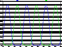
Here's the current through the output device emitter resistors...
Attachments
Member
Joined 2009
Paid Member
You might be interested to see Kenpeter's work regarding making the Allison to work at near class AB.
http://www.diyaudio.com/forums/showthread.php?postid=1886107#post1886107
Notice D1 and D2.
However, my experience on the sim tells me that going for non-switching is hardly worth it, and that the classic method of darlington EF + Vbe multiplier is the best thing for class AB. The switching harmonics are not really bad unless you're operating at 1MHz, or if your frontend is slow.
But I'm no expert here and differing opinions are to be found. Instead of taking anyone's advice, I suggest you sim, sim, and sim until you yourself know as good as anyone else what works well. Creativity is very underrated.
- keantoken
Member
Joined 2009
Paid Member
keantoken said:... my experience on the sim tells me that going for non-switching is hardly worth it, and that the classic method of darlington EF + Vbe multiplier is the best thing for class AB.
This appears consistent with my simulations.
In fact, I am now leaning strongly towards a CFP driver stage (aka Roender etc.) with an EF output as a better solution - allowing the drivers to buffer the front end from the output non-linearities and leaving the output stage alone.
Waveborne's AB may have a slightly less smooth crossing,
but his output stage also has the better soft clip function.
By "better" than mine, I mean soft even when clipped by
crazy load impedance... Not mere squashing of the input
waveform. Its a very important advantage he has...
The Schottky's you refer to, are only needed for AB if you
have "corrected" the complimentary nonlinearities out of
your output transistor's emitters...
A fixed voltage span across error corrected emitters as we
did with the Allison, is a whole different game than a fixed
voltage span across base drives... I'm not sure the same
diode trick I've used for Allison AB is helpful in other types
of outputs that already have complimenting nonlinearities.
Of course, it may be easier to match a pair of N Schottkys
to the same non-linear curve, than complimenting N and P
in three terminal devices...
The whole trick with AB, is that quiescent current is less
than at full swing. You need some non-linearity to shape
and smooth that crossing, linear math only adds up for
Class A.
Member
Joined 2009
Paid Member
I've had a look at the Allison output. And I've read more on Fd Fwd and Error correction. I'm not sure I fully understand the Allison output structure.
The concern I have with the Wavebourn output structure is that I have not seen low distortion in my sims at low signal levels. I love the soft clipping at high signal levels but not at the expense of the low signal levels where most of my listening will likely occur.
A far bigger problem is my limited knowledge and experience. I can only get so far before I hit problems due to a lack of understanding. I'd appreciate any help with getting past these roadblocks.
Perhaps the 'super A' non-switching output is not providing the anticipated benefit. But the original aim with this thread was to look at non-switching based on the Blomley method - where the output stage is actually supposed to operate in a current mode.
So I have made up a simulation of a current amplifier output with a voltage input. It produces low distortion in my sims at low signal levels. Clipping behaviour is awful but that's something to look at another day. The big problem and it is clearly something darn STUPID that I'm doing - the simulation only works with the default transistors in Spice. As soon as I try to use a model of a real device the results fall apart. I never saw this with the voltage mode output structures I have simmed in the past so I don't understand what I'm missing.
I'd appreciate some help with this one, it's got to be something stupid.
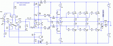
I'll post a few bits and pieces for viewing: First the schematic
Attachments
Member
Joined 2009
Paid Member
Bigun said:I've had a look at the Allison output. And I've read more on Fd Fwd and Error correction. I'm not sure I fully understand the Allison output structure.
The concern I have with the Wavebourn output structure is that I have not seen low distortion in my sims at low signal levels. I love the soft clipping at high signal levels but not at the expense of the low signal levels where most of my listening will likely occur.
A far bigger problem is my limited knowledge and experience. I can only get so far before I hit problems due to a lack of understanding. I'd appreciate any help with getting past these roadblocks.
Perhaps the 'super A' non-switching output is not providing the anticipated benefit. But the original aim with this thread was to look at non-switching based on the Blomley method - where the output stage is actually supposed to operate in a current mode.
So I have made up a simulation of a current amplifier output with a voltage input. It produces low distortion in my sims at low signal levels. Clipping behaviour is awful but that's something to look at another day. The big problem and it is clearly something darn STUPID that I'm doing - the simulation only works with the default transistors in Spice. As soon as I try to use a model of a real device the results fall apart. I never saw this with the voltage mode output structures I have simmed in the past so I don't understand what I'm missing.
I'd appreciate some help with this one, it's got to be something stupid.
I'll post a few bits and pieces for viewing: First the schematic
A note on the input VAS: the collectors of these transistors have no Vce, and so you will easily drive one transistor to saturation. Maybe you should try diodes in series with the bases?
Also, when you just leave the transistor models as NPN or PNP instead of specifying the model, it looks like LTSpice defaults to models of perfect transistors. This, obviously, will make your circuits impressive and ingenious in all ways.
It doesn't seem like it will work so good in real life though...
This circuit relies on Hfe to maintain the bias of the output devices, something that's not recommended.
I won't tell you it's a bad idea, because people have told me this and been wrong.
- keantoken
Member
Joined 2009
Paid Member
Good question - these two devices are the 'magic' that make this amp work for voltage inputs.
The basic design is a current amplifier. Q40/41 are the input devices and essentially split the current +ve going and -ve going. The current has 'no way out' except through the output stage so the total current going into the load is virtually distortion free providing that you use 'ideal transistors'. In fact the distortion profile of the current going into Q40/41 emitters is reproduced very accurately at the output load.
Since the input will in reality be a voltage I needed a voltage to current converter. Now this is not as easy as it seems. A simple resistor feed into Q40/41 doesn't work, it's too non-ideal and you end up pushing a lot of distortion into the amplifier. I looked at several alternatives (including the venerable LTP) but most were non-ideal or suffered from too much offset.
However, Q46/47 present a nice simple current source to the amplifier. The amplifier needs a +ve and -ve current input wrt ground. Q46 pulls current from the amplifier that it sinks to the -ve rail and Q47 injects positive current sourced from the +ve rail. Hence both collectors are connected to the amplifier input. It also provides for a low input current because most of the base current for Q46 is supplied from the base of Q47 and vice-versa. The signal input is a very tiny current. This is key, it is why this V-I converter has such low distortion going into the amp.
I see you're trying brand new ideas... this is very good to you and to all forum
including myself of course.
Interesting, you have tried a Fet, as i could see.... have you built to listen?....how it sounded with the Fet.... was strange?.. a little bit alike mufled....not really..seems good treble but the speaker cloth grille beeing so absorbing...alike a blanked over the speaker?.... sometimes i have felt this way...and because of that i give up to Fets.... they are good to switching.... into class D they are perfect as i could see.
Must be carefull... simulators turn us addicted, and we go simulating and simulating and not building...and we finally go believing virtual reality is the same as the real world...and it is not!... building, sometimes bad simulation sounds great and good simulation sounds terrible.... but it is not always this way.
Nice ideas...the sliding bias from Technics...the use of transistors to compensate...nice ideas...the input is Hugh Dean style...Doctor Self style...Hugh had used long time ago something alike...sligtly different only..other values i think...i have also used into Precision.... works fine..but i already know how sounds.
But you are tweaking VAS and the output..this is very good...something really brand new will appear soon for us.
I cannot see your files... txt and the other one i cannot open...if you do not mind, try to give us GIF or JPEG.... at least to me is easier to see your images... i have tried here, at paint, wordpad and Word and i could not open..... these files..what program they belong?
I thank you very much... reading the harry i had fun, was nice to see your efforts and something nice appearing.
btw....Hugh told me something to use into the VAS to turn it more stable and less dependent to the output circuit and load... i cannot say as i do not know if was a secret or not... ask Hugh how to turn VAS load independent.... maybe he can talk about...and i will be listen each one of his words...always carries a lot of good things to us...we must only be attention... seems we can improve VAS performance a lot... and solution was not fet or double transistors, or tripple transistors or darlington of voltage stabilization (zener) in some points..... was a nice idea.... simple and clever.
Sometimes, to have conversations with Hugh is a big problem..he is plenty of good ideas.... and this way we obtain important tips and tricks that we can use to increase amplifier's performance..but those things are his property...so... we can know but you cannot use...as i love to share, this turns me in a very bad sittuation..... knowing how to improve and cannot use.... better not to know... we can realise by ourselves and this way we do not invade intelectual properties.
regards,
Carlos
Member
Joined 2009
Paid Member
Carlos - thanks for the kind words.
I haven't tried the FET, am still playing with these ideas but am very curious about these parts. Some people love them, others don't. Because they are different from BJT I feel that they must have something to offer me, if used correctly. Where did you use the FET, only in LTP, or did you try in the VAS, or the Output ? ClassD is the future, but for DIY it is beyond my skills as they are today. I already have some ideas of how to use ClassD inside my amps, but I don't know how to realize these ideas.
It's very good advice you are giving. I have to finish my TGM project before I build some more things, but in the moments I have spare I am hoping to keep learning so that I can decide on what I will build next and so I fall victim to those simulations that tell us lies when we aren't carefull...but we keep wanting to use them.
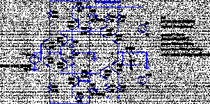
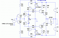
unfortunately I have a mixture of PC and Mac and things get a bit messy. I wanted to post the simulation file so others might try it and help me. But the Forum doesn't allow this kind of file type. However, if you change the file extension to .txt it fools the Forum and allows the file to be posted. To use the file it is only necessary to change the file extension back to .asc. In Windows you have to go to 'Tools' and then 'Folder Options' and the tab 'View' and then you uncheck the box that says 'Hide extensions for known file types'. Anyhow, I am attaching the diagram for the sliding bias circuit, the one with non-switching outputs. It took me some time to understand this as copying it from places on the web didn't yield results and I had to work it out from the beginning.
Has anyone built this type of non-switching output - how did it sound ???
destroyer X said:Interesting, you have tried a Fet, as i could see.... have you built to listen?....how it sounded with the Fet.... was strange?.. a little bit alike mufled....not really..seems good treble but the speaker cloth grille beeing so absorbing...alike a blanked over the speaker?.... sometimes i have felt this way...and because of that i give up to Fets.... they are good to switching.... into class D they are perfect as i could see.
I haven't tried the FET, am still playing with these ideas but am very curious about these parts. Some people love them, others don't. Because they are different from BJT I feel that they must have something to offer me, if used correctly. Where did you use the FET, only in LTP, or did you try in the VAS, or the Output ? ClassD is the future, but for DIY it is beyond my skills as they are today. I already have some ideas of how to use ClassD inside my amps, but I don't know how to realize these ideas.
Must be carefull... simulators turn us addicted, and we go simulating and simulating and not building...and we finally go believing virtual reality is the same as the real world...and it is not!... building, sometimes bad simulation sounds great and good simulation sounds terrible.... but it is not always this way.
It's very good advice you are giving. I have to finish my TGM project before I build some more things, but in the moments I have spare I am hoping to keep learning so that I can decide on what I will build next and so I fall victim to those simulations that tell us lies when we aren't carefull...but we keep wanting to use them.
I cannot see your files... txt and the other one i cannot open...if you do not mind, try to give us GIF or JPEG....
unfortunately I have a mixture of PC and Mac and things get a bit messy. I wanted to post the simulation file so others might try it and help me. But the Forum doesn't allow this kind of file type. However, if you change the file extension to .txt it fools the Forum and allows the file to be posted. To use the file it is only necessary to change the file extension back to .asc. In Windows you have to go to 'Tools' and then 'Folder Options' and the tab 'View' and then you uncheck the box that says 'Hide extensions for known file types'. Anyhow, I am attaching the diagram for the sliding bias circuit, the one with non-switching outputs. It took me some time to understand this as copying it from places on the web didn't yield results and I had to work it out from the beginning.
Has anyone built this type of non-switching output - how did it sound ???
Attachments
Member
Joined 2009
Paid Member
Re: I see you're trying brand new ideas... this is very good to you and to all forum
I'm glad about this.
I am still wondering about my dream of a current amplifier, if the realities of real-world devices can be overcome.
With the default spice models in my voltage mode amplifiers I always saw distortion. Adding in real models improved the accuracy but didn't produce a large degradation. With the current amp it changes drastically and it's a real shame.
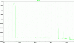
Here's the FFT of the current amplifier from the default spice models - you will agree that it makes for a very compelling design approach
destroyer X said:I thank you very much... reading the harry i had fun, was nice to see your efforts and something nice appearing.
I'm glad about this.
I am still wondering about my dream of a current amplifier, if the realities of real-world devices can be overcome.
With the default spice models in my voltage mode amplifiers I always saw distortion. Adding in real models improved the accuracy but didn't produce a large degradation. With the current amp it changes drastically and it's a real shame.
Here's the FFT of the current amplifier from the default spice models - you will agree that it makes for a very compelling design approach
Attachments
Member
Joined 2009
Paid Member
- Status
- This old topic is closed. If you want to reopen this topic, contact a moderator using the "Report Post" button.
- Home
- Amplifiers
- Solid State
- new amp... HARRY 77
