Owe troystg an apology & mini-A guys thanks
Yeah, I shouldn't have jumped all over troystg cause 1) it was a simple mistake & 2) BrianGT's PS PCB BOM is pretty much dead simple.
And any PS BOM is full of variables (xfmr secondaries, what builder is shooting for, filtering, LED brightness, etc.) See? At least I *think* I'm learning")
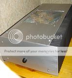
Anyway, wanted to show my absolute noob & mostly cheapo mini-A build.

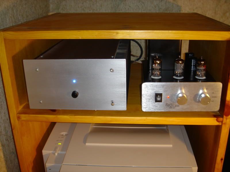
It's alive! And working very well I might add. Notes:
- Yeah, spare cheap fleabay mis-matched heatsinks add to the uniqueness
- that's the fleabay 16-0-16 300VA that should have been the 15-0-15 200VA. As is 21V .8A draw X 2 per side & I can still hold the sinks for 5-10 secs after an hour & is about as far as one should push those 2 devices I'd think.
- that's a SOHA headamp w/12-sec output delay relay acting as a preamp... And it's making a darn nice one IMO so far.
- MOSFETs matched from tech-diy made 1 less thing to worry about (DC offset quickly drops to < 15 mv).
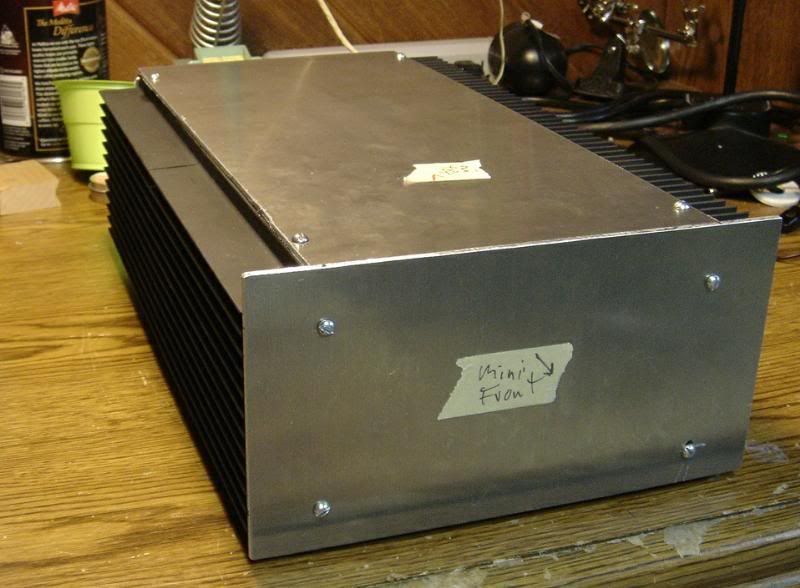
Empty case ready for boards, holes & filing/sanding.
- .12 plates cut w/80-tooth non-ferrous blade on table saw
- yes, I used a very lite coat of high temp grill paint to make the mismatched HS a little more matched.
Good stuff & might be done this weekend...
Thanks again to Mr. Pass, Brian & others involved.
Yeah, I shouldn't have jumped all over troystg cause 1) it was a simple mistake & 2) BrianGT's PS PCB BOM is pretty much dead simple.
And any PS BOM is full of variables (xfmr secondaries, what builder is shooting for, filtering, LED brightness, etc.) See? At least I *think* I'm learning
Anyway, wanted to show my absolute noob & mostly cheapo mini-A build.
It's alive! And working very well I might add. Notes:
- Yeah, spare cheap fleabay mis-matched heatsinks add to the uniqueness
- that's the fleabay 16-0-16 300VA that should have been the 15-0-15 200VA. As is 21V .8A draw X 2 per side & I can still hold the sinks for 5-10 secs after an hour & is about as far as one should push those 2 devices I'd think.
- that's a SOHA headamp w/12-sec output delay relay acting as a preamp... And it's making a darn nice one IMO so far.
- MOSFETs matched from tech-diy made 1 less thing to worry about (DC offset quickly drops to < 15 mv).
Empty case ready for boards, holes & filing/sanding.
- .12 plates cut w/80-tooth non-ferrous blade on table saw
- yes, I used a very lite coat of high temp grill paint to make the mismatched HS a little more matched.
Good stuff & might be done this weekend...
Thanks again to Mr. Pass, Brian & others involved.
troystg said:No appologies needed, and congratulations on your build!
Thanks! Yep, got it done yesterday... Sounding good & temporarily using Radii pre
troystg said:Yes, we should all be thankful to Mr. Pass, Mr. Grey and BrianGT. All VERY fine gentlemen. The world is a better place with them in it.
YES, if naming names to thank, mustn't leave out Grey (GRollins)!
Couple more tidbits I've learned...
Me being new to Class A SS, I've made a couple noob discoveries & changes... So this is for other noobs & maybe as entertainment for seasoned builders
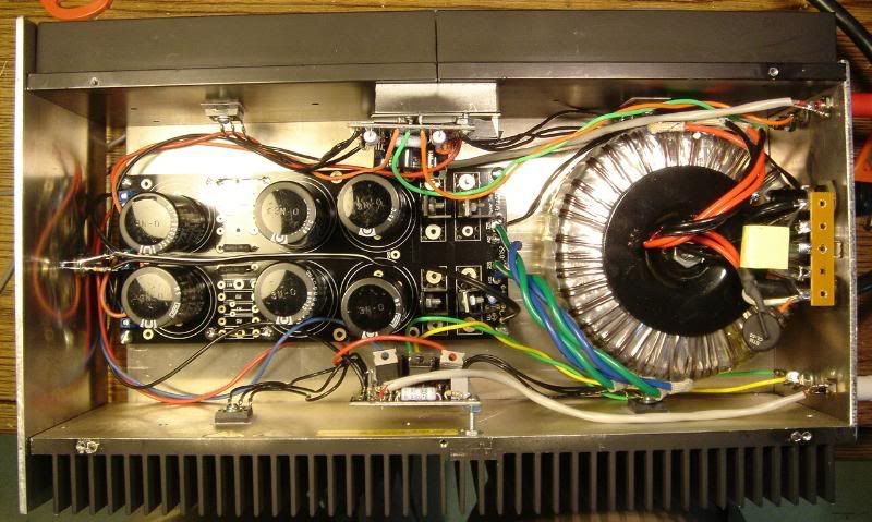
> my "As is 21V .8A draw X 2 per side.." Yeah, that's not really ideal for these output devices. Should draw at least 1A so I raised R13 to about 150k to get my build drawing 1.2A per rail per side. This got each fet to 25W idle (into the bottom of its "sweet" range from what I've read).
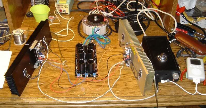
I used too small TO220 sinks I had on hand on the rectifiers (too hot to touch) as can be seen from this bench pic:

and bought some taller solid alum ones. Although the too large transfo is not wedged against fets, its real close but amp is still dead quiet. BTW, this is a scrap build & the scrap dictated its size.
Well, even with 1/2" slots in the bottom front & back top, the thing was an oven So used screen from $1 kitchen strainer & hacked a nice, big hole in the top. Now I think its done
Loved the tube pre/miniA/Hornshoppe combo... While it lasted that is. Found out the hard way that my new-to-me tube pre had nasty DC offset for a bit at turn on & turn off. It took only one out-of-order power up to fry the FE126s in my Hornshoppe horns But, Ed is coming to the rescue w/a new pair of matched & treated drivers for about the same price as the raw drivers themselves. Great guy that Ed.
Since added a full minute turn on muting delay (w/instant off) to my tube pre outs (based on a simple delay circuit).
Lessons learned for sure.
Me being new to Class A SS, I've made a couple noob discoveries & changes... So this is for other noobs & maybe as entertainment for seasoned builders
> my "As is 21V .8A draw X 2 per side.." Yeah, that's not really ideal for these output devices. Should draw at least 1A so I raised R13 to about 150k to get my build drawing 1.2A per rail per side. This got each fet to 25W idle (into the bottom of its "sweet" range from what I've read).
I used too small TO220 sinks I had on hand on the rectifiers (too hot to touch) as can be seen from this bench pic:
and bought some taller solid alum ones. Although the too large transfo is not wedged against fets, its real close but amp is still dead quiet. BTW, this is a scrap build & the scrap dictated its size.
Well, even with 1/2" slots in the bottom front & back top, the thing was an oven
So used screen from $1 kitchen strainer & hacked a nice, big hole in the top. Now I think its done 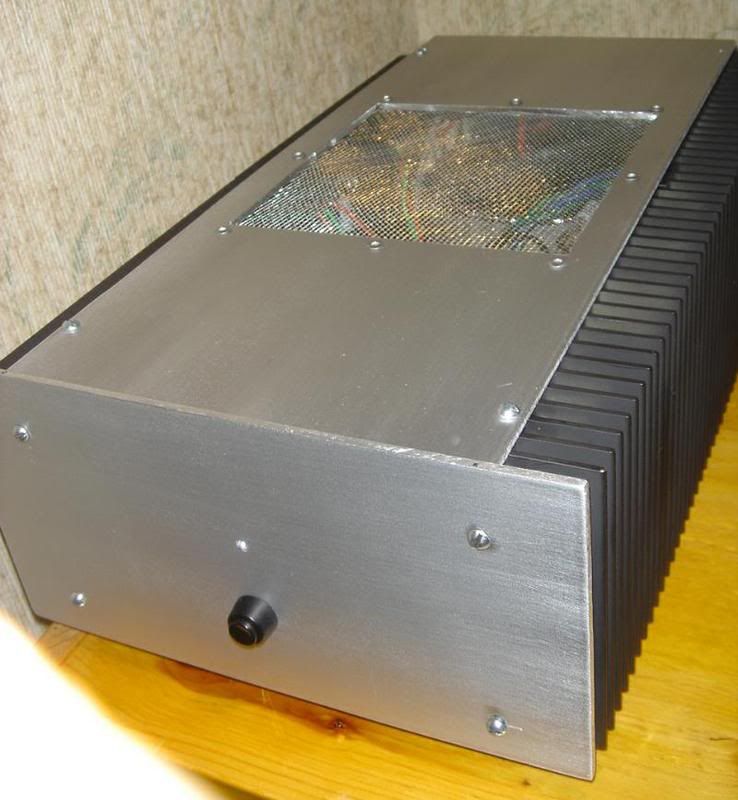
Loved the tube pre/miniA/Hornshoppe combo... While it lasted that is. Found out the hard way that my new-to-me tube pre had nasty DC offset for a bit at turn on & turn off. It took only one out-of-order power up to fry the FE126s in my Hornshoppe horns
But, Ed is coming to the rescue w/a new pair of matched & treated drivers for about the same price as the raw drivers themselves. Great guy that Ed.Since added a full minute turn on muting delay (w/instant off) to my tube pre outs (based on a simple delay circuit).
Lessons learned for sure.
Matched ouput fets on A30
Hi everyone...
I am finally at the point of finishing my A30 proyect which started about 3 years ago... its been a long time. I was in the original group buy in this thread and I have the boards all stuffed only the output fets are left.
I got he parts from jason´s kits and I have all 12 fets in matched pairs.... but only now I am thinking that I have sets of 3 fets ... so I am not really sure how to use these matched pairs.
Should it be
Pair 1 - Q8, Q9
Pari 2 - Q10, Q11
Pair 3 - Q12, Q13
or
should I have four sets of 3 matched fets, each set for Q8, 10, 12 and the other for Q9, 11, 13 ....
please advice...
thanks.

matching
The 'top' fets need to be matched to each other, and the bottom fets need to be matched to each other. Thus if you are using 6 fets per channel total, three for the current source (top) and three for the output device (bottom), you'd need two groups of three...I don't think there is anything to be gained from matching across these groups.
IIRC the input pair should be matched too.
HTH
Stuart
thanks
thanks guys.... that is what I thought from the same spreadsheet that korben shows, but since I got only matched pairs with my parts kit I thought I might be wrong.
So, Jason.. (jleaman) ... why was I sent matched pairs it sets of 3 are needed.... I know this is an old group buy but I would like to know from you or anyone else that was in the same buy.... maybe I am missing something here.
thanks again...
Re: thanks
I matched the FETs for Jason and I can assure you it is very problematic to match 6 devices indentically. I started with a batch size of 1000 all from the same date code, I special ordered them that way. I measured the VGS on all 1000 and then repacked them into kits for Jason. In 99% of the kits the devices were within .005 of each other. I think even Mr. pass uses a figure of .020 as an acceptable tolerance.
Can you tell me what the numbers were on the little white stickers?
Anthony
rebojorge said:thanks guys.... that is what I thought from the same spreadsheet that korben shows, but since I got only matched pairs with my parts kit I thought I might be wrong.
So, Jason.. (jleaman) ... why was I sent matched pairs it sets of 3 are needed.... I know this is an old group buy but I would like to know from you or anyone else that was in the same buy.... maybe I am missing something here.
thanks again...
I matched the FETs for Jason and I can assure you it is very problematic to match 6 devices indentically. I started with a batch size of 1000 all from the same date code, I special ordered them that way. I measured the VGS on all 1000 and then repacked them into kits for Jason. In 99% of the kits the devices were within .005 of each other. I think even Mr. pass uses a figure of .020 as an acceptable tolerance.
Can you tell me what the numbers were on the little white stickers?
Anthony
rebojorge said:Thanks Coulomb...
I don´t have them with me right now but if I remember correctly I have
Pair - Number
1 - 400
2 - 406
3 - 408
4 - 413
5 - 419
6 - ?... can´t remember this last one but it is within this range.
Are these numbers millivolts?
thanks!
Yes they are mV. You can easily use 123 as one side and 456 as the other IMHO.
Anthony
rebojorge said:Thanks Anthony...
I had a chance to check and I did not get white stickers.... on my mosfets I have red stickers and I did not get IRF244, I got IRFP140N instead.
Are these the devices you matched?
Yes I matched those as well from a lot of 500.
Regards
Anthony
Having just ordered some Mini Aleph boards from Brian (and hoping he still has some!) I have a couple of questions as I order parts.
1) What is the gain of the amp and how is it set? If I understand the circuit its set by feedback resistors R15 and R9 giving gain of 11 (could be 10?). Can the gain be changed (increased) and if so what are the limits and which resistor is changed? Do I reduce feedback by increasing R15?
2) Power supply. Gonna get 6 @ 22000uf caps. Using PSUD you get greatly reduced ripple with CRCRC than CCRC (.47ohm for the R) for which Brian's boards are designed. Any problems with the extra R other than slightly more voltage drop? I had considered CLC but decided against this after bit more reading - low benefits against other possible problems with magnetic feilds.
Thanks.
ChrisMmm said:I also want to use it with unbalanced inputs - I believe you short -IN to SG. Is that correct, anything else need be done?
Thanks again
correct
- Status
- This old topic is closed. If you want to reopen this topic, contact a moderator using the "Report Post" button.
- Home
- Amplifiers
- Pass Labs
- New Aleph Mini PCB GB