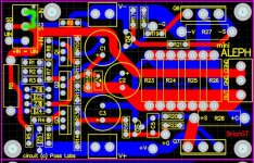
jleaman said:Building the Aleph's with brian's boards is really simple and 100% ready to turn on.
After having gone thru the process I agree 100% with this and your earlier comments about bad/wrong components being the only reason they won't start up successfully. I don't think the jumper location suggested (in the links I posted earlier) to allow checking voltages without output boards actually worked exactly as advertised. It did allow me to verify a number of points in the circuit were on spec. Beyond that it seems to be a case of double check wiring/component location and orientation and throw the switch.

Hello, all --
I've gathered almost every part to build my own Mini.
My heatsinks are way too small and inefficient (three 4"x3" at 15W), so I'm going to implement a quiet HDD or CPU fan, as indicated by the photo, until I can get some large heatsinks for a low price. What do you all think about my plan to mount the FETS on a P4 or better heatsink? I will add another one for the other channels' FETS.
The scotch tape is where the toroid will be placed once I receive it.
Like my "poor man's" PCBs?") The print outs for the channels are bit larger than Brian's, so I have more room to place things.
The print outs for the channels are bit larger than Brian's, so I have more room to place things.
I've gathered almost every part to build my own Mini.
An externally hosted image should be here but it was not working when we last tested it.
My heatsinks are way too small and inefficient (three 4"x3" at 15W), so I'm going to implement a quiet HDD or CPU fan, as indicated by the photo, until I can get some large heatsinks for a low price. What do you all think about my plan to mount the FETS on a P4 or better heatsink? I will add another one for the other channels' FETS.
The scotch tape is where the toroid will be placed once I receive it.
Like my "poor man's" PCBs?
The print outs for the channels are bit larger than Brian's, so I have more room to place things.Banned
Joined 2002
applebook said:Hello, all --
I've gathered almost every part to build my own Mini.
An externally hosted image should be here but it was not working when we last tested it.
My heatsinks are way too small and inefficient (three 4"x3" at 15W), so I'm going to implement a quiet HDD or CPU fan, as indicated by the photo, until I can get some large heatsinks for a low price. What do you all think about my plan to mount the FETS on a P4 or better heatsink? I will add another one for the other channels' FETS.
The scotch tape is where the toroid will be placed once I receive it.
Like my "poor man's" PCBs?
Um, if you plan to use that cpu heat sink to sink the alephs they will blow up. WAy to small.. go on ebay and get a pair of heat sinks. I bought 4 for really cheap. If you need the link let me know. They are cheap and work great for aleph mini's and other alephs.
Don't under heat-sink alephs they will blow up.
What about 2 FETS on each 15W heatsink? I don't know what the rating on the P4 heatsink is.
Please pass along that eBay seller: jville2@shaw.ca
BTW, where is C6 on the PCB? I can't seem to locate it anywhere.
Please pass along that eBay seller: jville2@shaw.ca
BTW, where is C6 on the PCB? I can't seem to locate it anywhere.
Banned
Joined 2002
applebook said:What about 2 FETS on each 15W heatsink? I don't know what the rating on the P4 heatsink is.
Please pass along that eBay seller: jville2@shaw.ca
BTW, where is C6 on the PCB? I can't seem to locate it anywhere.
You got mail.
C6 sounds like it is near the front of the board. maybe you have a older version of the ( printed on paper ) version of the layout. Check the actuall board. jase.
Link for heat sinks for any one else..
http://cgi.ebay.com/HEATSINK-ALUMIN...DVWQQrdZ1QQcmdZViewItem?hash=item170058199408
Thanks, Jason.
The board that I'm using is http://www.diyamps.com/aleph/images/miniAleph-PCB.gif
which I now see is out of date. Doh! Good thing I didn't solder anything yet.
Brian added C6 in between R5 and Z5. Other than that, I see now other changes.
A couple of questions --
1. C1 should be reversed from this layout? http://www.diyamps.com/aleph/images/miniAleph-PCB.gif
2. Which path is C6 connected to? Judging by the pictures, C6 is a bridge between R5 and Z5 and should be connected to these two points?
Best regards - Derek
Banned
Joined 2002
applebook said:so that's about 45 Watts with the fan? That'd be very nice if I planned on actually its fan.
The intel heat sinks will not keep your alephs cool enough ( properly ) just buy a pair of those heat sinks i posted a link to.
applebook said:Yep, I purchased a pair. Shipping is cheap too. Thanks again.
Just curious, how much was shipping for a pair?
Cheers,
Dennis
Hi ...
I have two questions ;
- how do you connect unbalanced signal to input ? do I need to short ground to - ( of XLR ) ( place jumper from SG to -In )
- and is there way to optimize Aleph Mini for 10W on 4 Ohm ( I need mini to drive 4 ohm tweeter ( scan speak 2904/7000 )
Thanks
I have two questions ;
- how do you connect unbalanced signal to input ? do I need to short ground to - ( of XLR ) ( place jumper from SG to -In )
- and is there way to optimize Aleph Mini for 10W on 4 Ohm ( I need mini to drive 4 ohm tweeter ( scan speak 2904/7000 )
Thanks
Banned
Joined 2002
yoke said:Hi ...
I have two questions ;
- how do you connect unbalanced signal to input ? do I need to short ground to - ( of XLR ) ( place jumper from SG to -In )
- and is there way to optimize Aleph Mini for 10W on 4 Ohm ( I need mini to drive 4 ohm tweeter ( scan speak 2904/7000 )
Thanks
See Picture
And with the min alephs the best thing about them is you can just change heatsink / psu voltage up / down to get more less power.
if you want 10watts id do about 15-Volt rails. Transformer before recitification is about 12-0-12 They sell them on ebay for about 32$
Attachments
Thanks Jason for replay
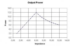
I have Aleph Power and Dissipation Spreadsheet from wuffwaff and when I enter 15V or 18V ( small diference in power at 4 Ohm ) I get around 8W ...
The picture below show 15V and 1A ...
From the sime spreadsheet, if I would like more power at 4 Ohm I would nead to rise bias ...
Is this right ? ...
what is the minimum recomended voltage for IRFP044 operation ?
my heatsink could only take up to 18-19W ... so if I would rise bias I would nead to lover voltage to stay inside those 18-19W
Attachments
Banned
Joined 2002
I have another question, will this EI 15W 80Ma transformer work? http://www.rpelectronics.com/English/Content/Items/125ESE.asp
I've seen another builder make his/her Mini with those exact specs but want to be sure.
Toroid transformers are ideal with audiophiles, but Antek is taking ridiculously long and is asking for an additional $16 shipping even though I've already paid $25 for shipping (as per their original request).
I've seen another builder make his/her Mini with those exact specs but want to be sure.
Toroid transformers are ideal with audiophiles, but Antek is taking ridiculously long and is asking for an additional $16 shipping even though I've already paid $25 for shipping (as per their original request).
You're right. Here's the correct one: http://www.rpelectronics.com/English/Content/Items/166R12.asp
yoke said:Thanks Jason for replay
I have Aleph Power and Dissipation Spreadsheet from wuffwaff and when I enter 15V or 18V ( small diference in power at 4 Ohm ) I get around 8W ...
The picture below show 15V and 1A ...
From the sime spreadsheet, if I would like more power at 4 Ohm I would nead to rise bias ...
Is this right ? ...
what is the minimum recomended voltage for IRFP044 operation ?
my heatsink could only take up to 18-19W ... so if I would rise bias I would nead to lover voltage to stay inside those 18-19W
Hello Yoke,
As Jason mentioned, the best thing will be if you can
use larger heatsinks. (Perhaps use a fan?)
However, if you can only to dissipate 18W per
mosfet then I would perhaps try
12V @ 1.5A. Mr. Pass' mosfet testing article
( http://passdiy.com/pdf/mos.pdf ) shows that the
distortion goes up with decreasing
voltage and goes down with increasing bias.
Then there's the matter of the circuit itself. IIRC,
the biasing circuit of the front end differential
pair will stop working below a certain voltage.
You're right about connecting an unbalanced
signal. Simply short the negative connection
of the XLR to ground and you're all set.
Cheers,
Dennis
- Status
- This old topic is closed. If you want to reopen this topic, contact a moderator using the "Report Post" button.
- Home
- Amplifiers
- Pass Labs
- New Aleph Mini PCB GB