I tried...
...about 1.5 times the idle current with excellent results, ie measured results eventually matched simulated results. Since an aleph can push more current than implied by a 'normal' class A amp, I chose to simulate with a little more than the idle current, but it really depends on how much gain you build into the aleph current source...
Stuart
...depends...
... I used a different set of params than are typical for an aleph30, for each channel my idle current was ~1.8A, so I simulated with 2.7, and seemed to get excellent correlation between simulation and reality...My dissipation for 2 channels was about 300w.
I had 68kuF-2.7mH-68kuF and ended up with <10mv ripple at fullpower into 8ohms..
Stuart
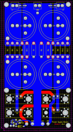
Here is an idea for a revised power supply board. I changed the capacitor footprint to allow for the larger 40mm 4 pin capacitors as well as the previous 20-35mm caps. Here is the digikey page for the Panasonic TS-HA, which have the larger footprint:
http://dkc3.digikey.com/PDF/T051/0880.pdf
The capacitors come in larger sizes, and this should make this a more versatile setup.
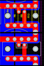
For the CRC filter, I decided that multiple 3w resistors in parallel (5 per rail) would work better than a larger resistor, as done with the output resistors on the amplifier pcb. There are still pads available for wiring up a CLC filter.
I reduced the number of caps to 2 per rail, due to the option of being able to run larger capacitors.
Ventilation holes were also added below the heatsinks.
Let me know if you have any feedback. I am going to order boards soon, and am trying hard to get these boards as perfect as possible.
--
Brian
Attachments
Banned
Joined 2002
jleaman said:Here is some feed back.
WHAT am i going to tell all the people that just paid me for there kits ? the caps are different.
The other caps still work. This board is just more versatile.
--
Brian
Banned
Joined 2002
I like the new board Brian, the larger caps are a nice option. The problem is for people who perscribe to the theory that smaller caps have less ESR and react to current fluctuations faster then large caps, they can no only put four caps on the board.
Is there a way you could put both footprints on the same board, 6 smaller caps or 4 larger ones? That way the user can populate the boards to his or her liking. If you juggle the real estate with enough finesse I am sure you could come up with some workable gemoetry.
Regards
Anthony
Is there a way you could put both footprints on the same board, 6 smaller caps or 4 larger ones? That way the user can populate the boards to his or her liking. If you juggle the real estate with enough finesse I am sure you could come up with some workable gemoetry.
Regards
Anthony
The new boards look great. I have to admit it would be good if possible to have both (4 or 6) config. I was thinking of using these boards for another project down the line.
I did a simulation using the new boards w/ the 40mm caps in Duncans psud2 if anyone is interested, you will need to download the freeware if you don't have it to view the attachment.
http://www.duncanamps.com/psud2/index.html
Stan
I did a simulation using the new boards w/ the 40mm caps in Duncans psud2 if anyone is interested, you will need to download the freeware if you don't have it to view the attachment.
http://www.duncanamps.com/psud2/index.html
Stan
Attachments
Jean said:I like this new revision of the power supply board also. My only suggestions would be, maybe allow the board to use to220 style resistors with same heatsinks as the diodes ? maybe 2 per rail ?
I could easily fit room for 1 heatsinked to-220 resistor per rail. Caddock MP930 resistors are rated at 30w when heatsinked, which is twice the rating than the 5 - 3w resistors in parallel.
I would still stick to 5 - 3w resistors, as I feel more comfortable having 5 components in parallel.
--
Brian
Attachments
Coulomb said:I like the new board Brian, the larger caps are a nice option. The problem is for people who perscribe to the theory that smaller caps have less ESR and react to current fluctuations faster then large caps, they can no only put four caps on the board.
Is there a way you could put both footprints on the same board, 6 smaller caps or 4 larger ones? That way the user can populate the boards to his or her liking. If you juggle the real estate with enough finesse I am sure you could come up with some workable gemoetry.
Regards
Anthony
The larger capacitors have a lower individual ESR than the smaller capacitors, so there is no advantage in terms of ESR using 6 TS-UP capacitors vs. 4 T-HA capacitors.
For the caps that I have here now:
10,000uF 50v TS-UP 35mm x 30mm
ESR @ 120hz = 0.036 ESR @ 20khz = 0.027
For an equivilant capacitance bank:
15,000uF 50v T-HA 35mm x 50mm
ESR @ 120hz = 0.022 ESR @ 20khz = 0.018
Run the numbers for the capacitor bank and you will see that the larger caps will allow for the same, if not lower ESR, since ESR is also a function of the capacitor size.
If you want to go for a significantly lower ESR bank, try paralleling a bunch of smaller Panasonic FC capacitors, but I feel that this is beyond the scope of this project.
Panasonic T-HA datasheet:
http://www.panasonic.com/industrial/components/pdf/pic_t-ha_series_dne.pdf
Panasonic TS-UP datasheet:
http://www.panasonic.com/industrial/components/pdf/pic_ts-up_series_dne.pdf
--
Brian
I like the board above. I have used 120,000 mfd Panasonic T-HA caps in the mini that I use at home with fantastic results. On this version of the board one could have 360,000 mfd per rail for a mini running +\- 15 volts. Now thats alot of total capacitance which will also have very low ESR!! I can vouch that just 1 pair of these caps in a mini sounds amazingly good, now thing three pair..... .
.
Mark
Mark
rick57 said:Readsy to pay, I went looking to check if prices are USD or $C, but couldn’t find it.
It’s also not where the prices are - on the Wiki(?)
What is it??
All prices are in USD for the PCB orders, which you can place on the website:
http://www.chipamp.com/aleph
--
Brian
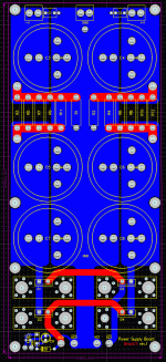
Alright, I have placed both layouts on my webpage:
Version 1a:
http://chipamp.com/diyaudio/ps1a.gif
6 capacitors, board size = 3.5" x 8"
Version 1b:
http://chipamp.com/diyaudio/ps1b.gif
4 capacitors, board size = 3.5" x 6.5"
The capacitor footprints on both layouts accept either the smaller 2-pin or larger 4-pin snap-in capacitors.
Both layouts will be modified to use a TO-220 CRC resistor:
http://www.diyaudio.com/forums/showthread.php?postid=612674#post612674
The only real issue with these boards is the extra 1.5" size of the 6 capacitor version.
I placed a poll on my website here:
http://www.briangt.com/gallery/PS-poll
Based on the feedback that I get, I will place the order.
I did some chassis measurements, and 3.5" x 8" works fine in my chassis.
--
Brian
rabstg said:Brian-
My 2 cents...
Please add at least another 2 holes on the grnd plane on the output side.. Maybe even a hole big enough for a bolt/nut combo.
There is always something else that needs a good ground point.
I will do this for the board. I had multiple output pads on the older board, but removed them during the redesign and forgot to add them again.
--
Brian
- Status
- This old topic is closed. If you want to reopen this topic, contact a moderator using the "Report Post" button.
- Home
- Amplifiers
- Pass Labs
- New Aleph Mini PCB GB


