"If I understand you correctly, the pos loop has a part outside the nfb loop. That means that the nfb cannot reduce the errors (distortion, freq response) in the part that is outside it. That doesn't seem like a good idea especially since pf generally aggravates the errors."
Yes you are right, that is not my amp. It's 1953 patent by John Miller and his 1950 article, could easy has another NFB in the front end though. But I think he didn't do it due gain limitation imposed by PF due transformer output, if OTL amp sure he can boost the gain further...
The 3rd point refer to my amp.
It would be nice to see some current waveforms for the top and bottom output tube sections in your amp, so as to determine what is going on as far as the two sections "cooperating" or "fighting". The NFB only cares about the final result, not how it gets there. So we have a poor understanding of what current is just passing through from - to + power supply rails. Just a couple of low Ohm resistors in the ground return leads of the + and - power supplies would allow easy scoping of the current sense signals.
It would be nice to see some current waveforms for the top and bottom output tube sections in your amp, so as to determine what is going on as far as the two sections "cooperating" or "fighting". The NFB only cares about the final result, not how it gets there. So we have a poor understanding of what current is just passing through from - to + power supply rails. Just a couple of low Ohm resistors in the ground return leads of the + and - power supplies would allow easy scoping of the current sense signals.
Right, I understand, I will take snapshot of the waveform on top of resistor R34 of V3 cathode and R37 of V4 cathode soon.
Today I done yet another experiment. I increase the value of R17 of V2 top to about 20K while R18 at 16.5K unchanged. The reason is that I always get positive DC offset in the output, with or without PF. This is because top tube is conducting less than the bottom tube so waveform is lopsided. Even with so high NFB, it still can not raise enough drive for top tube. Not only that the conduction angle is "shorten" early and the lower tube start to conduct earlier. That is why the crossover distortion is not visible under heavy clipping due "over" overlapping. After R17 is increased to 20K I got good DC offset and now you can clearly see the crossover during clipping right in the middle. That is more like Class AB, but the idle current could be reduced somewhat so yet increase some more efficiency.
This change has brought the amp with full control of NFB once again, sonic wise has improved.
I will post the snapshot later today.
Last edited:
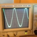

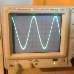
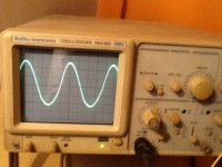
This current waveform of top and bottom tube 20*10 mV scale. Output level is just under clipping when the current waveform is taken. This is 10 tubes model 5 tubes each bank, current waveform is taken using floating scope across 1 ohm resistor in the cathode of one of tubes.
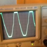
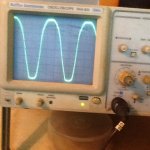
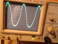
As you can see from 2nd snapshot in the last post, when driven further into clipping, crossover point shifted up further, meaning top is conducting lesser during this time due to loss of gain, as well as DC offset jumped to 1.2V at this point while normally just < 0.1-0.2V.
As you can see from 2nd snapshot in the last post, when driven further into clipping, crossover point shifted up further, meaning top is conducting lesser during this time due to loss of gain, as well as DC offset jumped to 1.2V at this point while normally just < 0.1-0.2V.
Attachments
" I'm assuming the operation at V2/bottom is class A, so there is no switching on/off of the PF."
I like to make clearer answer to this:
1) yes V2 is a Class A type.
2) V2 also drives the bottom tube
3) V2 also where PF is (solely) derived so it it important V2 output not be trimmed due addition load branching. So must have sufficient gain to minimize the loss. We experienced some difficulty in very low mu tube such as 5687, and so plate resistor in V2 needs adjusted to compensate for the loss. The value in original schematic works very well including 5687 (Have to adjust the PF resistor R16 and R26 to suit my latest is R26=500, R16=100K), the others remain unchanged.
4) It is debated as why PF should be derided from V2. Ideally NFB should be able to have full control under optimal condition, these conditions can be met easier with a bit higher gain tube, with low gain is it is a bit of challenge especially boosting to same higher level. It is important the condition be met before drawn conclusion. Since the bottom tube is a voltage follower and upper tube is cathode follower to begin with, V2 drive would be quite different from V2 top in turn of wave form shape since there are not the same output type so they have different gain at low output to nearly some gain at higher output. Still remember V2 bottom is sole point where PF is derived for top and bottom. If we maintain V2 bottom level as is (it signal level under NFB control through out), it appeared to me this PF so derived appeared to be have very good result.
5) You can see why in snapshot attached. The top part of wave form drives bottom tube and bottom part wave form (actually an inverted in V1 splitter for top tube drive, as the bottom part does not actually drive top tube, it is mirror of the actual arm drive the top tube). drives top output tube This is the kind of proportion we looking for.
Attachments
Last edited:
Thanks for all the photo measurements. Much clearer now how it is operating. The output currents indicate class aB operation of the output tubes. The NFB is swinging the drive signals asymmetrically to drive the cathode follower up top versus the grounded cathode stage on the bottom. The full NFB loop is performing the "voltage follower" function for the bottom output tube. Usually I think of a voltage follower as being a more local feedback loop.
In addition, I think what you have been saying (and I wasn't getting) then is that the PF assists "more" when the bottom output tube needs more drive signal (since the bottom V2 plate swings more then), so the PF is doing some of the output symmetry correction directly. It is an interesting approach. One might expect the adjustment of the PF gain to find an optimum level where it just exactly corrects the lower tube gain. Somewhat similar to the Error Correction (EC) technique used in SS amplifiers for fixing crossover, except here it is functioning with a large assymetry to fix.
This would be quite interesting to look at the output distortion directly with a differencing Op Amp, while adjusting the PF level to see if there is a best "null" error point for the PF.
The EC technique puts the PF correction in ahead of a local NFbk point (effectively changing the input signal), so that it can develop immense gain (recirculated PF leading to just short of infinite open loop gain) to overcome the error altogether at an adjusted "null". There is then a global NFbk loop around the EC loop to fine tune out any residuals and maintain stability. Your circuit's PF loop may still be operating as conventional PF with fixed gain, not sure at this point about the front end cathode PF injection. Finding an error "null" (optimum PF level) would indicate it is operating like EC.
Conventional PF would show asymptotically reducing distortion as the PF is increased. While EC would show an optimum PF point, and can actually invert the distortion if adjusted beyond the optimum level.
Last edited:
Late correction:
"the PF assists "more" when the bottom output tube needs more drive signal (since the bottom V2 plate swings more then), so the PF is doing some of the output symmetry correction directly."
should be:
"the PF assists "more" when the TOP output tube needs more drive signal (since the bottom V2 plate also swings more then), so the PF is doing some of the output symmetry correction directly."
also, EC is just used in some SS amps, not all.
Setting it up like an EC loop may just entail reaching the point where the gain around the PF loop is at unity in closed loop. (giving inf. open loop gain)
Normally, EC or infinite PF open loop gain, requires additional (real) gain in the outer NFbk loop to keep it all under control (the NFbk loop then gets whatever open loop gain the PF loop provides + the additional gain). This condition is met when the bottom output tube is conducting, but is not met when the top (Cathode Follower, with gain less than 1.0) tube is conducting. So this probably will prevent (dis-allow) adjusting the PF gain up through the error null.
Last edited:
Normally, EC or infinite PF open loop gain, requires additional (real) gain in the outer “NFbk loop to keep it all under control (the NFbk loop then gets whatever open loop gain the PF loop provides + the additional gain). This condition is met when the bottom output tube is conducting, but is not met when the top (Cathode Follower, with gain less than 1.0) tube is conducting. So this probably will prevent (dis-allow) adjusting the PF gain up through the error null.”
Both tube will have about nearly same gain at high level output so EC condition can still be met?. In actual asymmetry transformer inter-stage coupled OTL as attached, both tube begin with voltage follower of same gain, so same drive level, so EC can be null so that is what you mean?
But ours begin with different gain but is relying on EC drive for different in gain adjustment, the difference is in the driver level, can we get error null this way?
I will post some snapshots for over PF driven output later to show the waveform distortion.
Attachments
Last edited:
"What if we provide additional gain to top tube by altering R17, so the open loop gain of both is same under PF control?"
Exactly what I was thinking. The PF loop gain can be adjusted to unity loop gain, no matter which output tube is conducting. So it is a matter of providing some extra V gain for the N Fdbk loop to always control that. The bottom output tube already provides some gain when it is conducting, just the top tube is short on gain. So increasing the driver gain to the top tube to match should be able to level the field. Only thing then is if the load Z varies, then the bottom tube could loose some gain at times. But it just needs to keep up some minimum gain.
Exactly what I was thinking. The PF loop gain can be adjusted to unity loop gain, no matter which output tube is conducting. So it is a matter of providing some extra V gain for the N Fdbk loop to always control that. The bottom output tube already provides some gain when it is conducting, just the top tube is short on gain. So increasing the driver gain to the top tube to match should be able to level the field. Only thing then is if the load Z varies, then the bottom tube could loose some gain at times. But it just needs to keep up some minimum gain.
Last edited:
Thank you, I think now the open loop is quite close due to the PF branch loss of bottom tube, no much I can do at this moment.
Now here are some figures I gather FYI, correct me if wrong.
Calculation for plate efficiency of output stage
Internal resistance 6C19p, 400±100 Ohm, expected Rp for 10 tubes 400/10=40, load is 8 ohms, assumed 25% plate efficiency.
0.25=8/(Rp+8)
0.25(Rp+8)=8
0.25Rp + 2 = 8
0.25Rp = 6
Actual Rp = 6/0.25 = 24
Verify it: 25% = (8(24+8))*100
Voltage gain enhancement by conductance cancellation in triode 5687 under full clipping gain is 280 (measured)
Mu = Gm x Rp
5687 gm = 0.01 mohms, Mu =20
Rp= mu / gm = 20/0.01=2K
boosted gain = 280, then Rp = 280/0.01=28K, gain increased 14 times
Last edited:
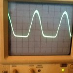
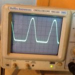
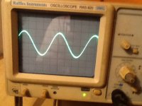
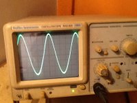
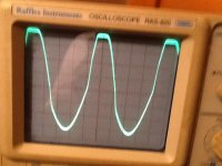
Here are snapshots of PF various amount of overdrive. Look like the bottom tube drive is losing some steam during medium to high level overdrive, appears quite normal up 30% PF overdrive. There are quite a bit of "positive" phase shift also at higher level.
Attachments
Last edited:
Resolve open loop gain difference
Last 2 days I seriously look at the best way to resolve the open loop gain for top and bottom. I found an easier way is to bootstrap V2 top using PF2 derived from V2 bottom plate. Two components C10 0.22uF and R27 1M are added. The V2 top is always high than V2 bottom even in open loop (PF1 open) with very little DC offset at full output, sonic wise also improved. New drawing is attached.
Last 2 days I seriously look at the best way to resolve the open loop gain for top and bottom. I found an easier way is to bootstrap V2 top using PF2 derived from V2 bottom plate. Two components C10 0.22uF and R27 1M are added. The V2 top is always high than V2 bottom even in open loop (PF1 open) with very little DC offset at full output, sonic wise also improved. New drawing is attached.
Attachments
Last edited:
PF2 will also feedback thru C5 to the splitter to act as N Fdbk there. Getting complicated now.
PF2 is basically making R8 act like a higher value load for the splitter. If PF2 does actually increase (via net Fdbk) the input signal to the top V2 driver tube, the driver must still be able to support the increased plate swing to drive the V3 follower.
This is getting to look like everything goes BUT the conventional bootstrap of the top V2 plate load from the output signal. The conventional bootstrap design would fix everything elegantly. You can still use the PF loop in the front end that way too, if you want the extra gain.
If you are evaluating the results by ear for each change, you are likely just increasing the 2nd harmonic distortion each time.
Last edited:
Oh yes, you're right, so I better move PF2 behind R23 1K, not in front of it, isolated it somewhat, that gives it better way to derive a final gain, we have to be very careful. Sonic wise I don't know if any difference between this and conventional bootstrap the convention does have weak point: change V2 top output impedance so gain likely to be affected by the load Z. Also hum would be different due to additional coupling capacitor and resistor, required the V2 bottom additional same value decoupling cap and resistor, not so straight forward and cost.
"If you are evaluating the results by ear for each change, you are likely just increasing the 2nd harmonic distortion each time"
The bass is more comfortable for my ear after this change. I am familiar how 2nd harmonic distortion sound like I supposed.
"If you are evaluating the results by ear for each change, you are likely just increasing the 2nd harmonic distortion each time"
The bass is more comfortable for my ear after this change. I am familiar how 2nd harmonic distortion sound like I supposed.
Last edited:
- Status
- This old topic is closed. If you want to reopen this topic, contact a moderator using the "Report Post" button.
- Home
- Amplifiers
- Tubes / Valves
- Negative Feedback Amplifier with embedded Positive Feedback Booster