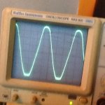
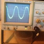
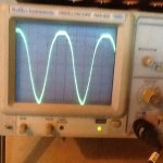
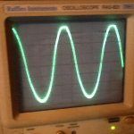
Here are some snapshots (sorry about the quality as it quite dark now). The output is about 40V-P-P(25W RMS) load is 8 Ohms (60W Dummy Load). The top and bottom tube is on 8*20 160V scale. As seen from snapshot the top tube drive level is about 110V P-P and bottom tube drive 160V P-P. This is after the last modification mentioned in this thread, V26 is 1K, R17 is 33K/2 2Watts and R18 (twice R17) is 33K/2Watts. These measurement are contradicting to conventional OTL amp, any thought? Maybe the bottom tube is conducting more than the top tube, etc..? I am still excited.
Attachments
Last edited:
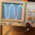
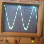
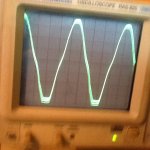
So I did another change: I revert back R18 to 33K/2 (16.5) so now is value as R17. I parallel a 1M resistor across the PF resistor R16 of 220K makes it about 180K, thereby increase PF drive to V1. The driver output (8*20V scale) is more less same level now. DCR is 0.05V at no output, raise to 1.2V at clipping as shown, drop to 0.6V just below clipping, this is an improvement over previous change.
Attached is snapshots.
Attached is snapshots.
Attachments
.... PF will increase gain only when there is input signal and attained certain maximum gain in V1 only, say 45. Therefore the maximum gain is 45* 10 =~450, initial gain is 70.
What do you think?
Based on the last experiment, at full output 25W clipping 8 ohms load, V1 is about 270 and V2 gain about 11 so 270*11 = ~3000 actual maximum gain
This is measured data: V1 in 50mV P-P, V1 out = 14V P-P, and V2 out 160V P-P
Last edited:
Why do you consider the PF to only begin when there is signal on V2? (agree there is no actual PF effect if the signal is zero, but the same could be said for the NF too) Are the V2 tube driver sections running in class aB or B?
I see now that the operation is significantly different from what I had originally envisioned. I was assuming that the top and bottom tube drive signals where being conditioned for symmetrical outputs via feedbacks, but obviously they are running quite asymmetric.
I suspect that the top output tube is running the show voltage-wise, and the bottom output tube is acting as a variable complementary current pull-down. No attempt being made to equalize the outputs (other than after the fact with neg. Fdbk). So likely they are running in class A most of the time, or at least during the crossover region. This would account for low crossover distortion. But would make for a lot of heat.
It would be instructive to leave the load connected, but replace the bottom tube with a resistor capable of supporting the idle current at crossover (zero volts output with no signal). Then take a scope trace.
Similarly, remove the top tube and replace it with a resistor capable of supporting zero signal idle current, with the bottom tube back in place. Then take a scope trace. This all being to determine what contribution each output tube is making to the output, and the class of operation or range of that.
If the output stage is running in class A all the time, it must be getting fairly hot for an OTL amp. Usually the high current requirements of OTL demand a near class B output stage with plenty of feedback to fix the crossover. The other issue would then be the output Z, with just the top follower setting that impedance level, along with the N feedback. OTL amps like the Circlotron try to use both output tubes in follower mode to reduce the output Z maximally, along with the N feedback.
If you have a current probe, or a differential probe, then the currents through R34 and R35 could be viewed on the scope, instead of the R substitution idea. A simpler measurement. Or maybe put some low Ohm resistors in place of, or series with, the F1 and F2 fuses for scope measurement.
Last edited:
"Why do you consider the PF to only begin when there is signal on V2? (agree there is no actual PF effect if the signal is zero, but the same could be said for the NF too)"
Because its actual open loop gain (i.e when NFB link is removed and PF link connected) can not be measured as it turned into an oscillator and open loop of oscillator is not the same as open loop of preamp such as one intended for NF. There will be an initial gain once inside the NF loop and initial gain is V1*V2 which coin sized with original gain which is low. The NF preamp open loop gain is the original gain which is very high to begin with, although reduce in NF loop, the initial gain is not the same as original gain. Do you think otherwise?
"I suspect that the top output tube is running the show voltage-wise, and the bottom output tube is acting as a variable complementary current pull-down. No attempt being made to equalize the outputs (other than after the fact with neg. Fdbk). So likely they are running in class A most of the time, or at least during the crossover region. This would account for low crossover distortion. But would make for a lot of heat. "
Very low bias only 40mA per tube, 4 tubes each bank. So not Class A, Class AB maybe. In the first experiment it was lower tube that do most of work as overlap with top tube, as I can almost detect the crossover point in my scope somehow, may be you can see it when closely examine the photos - the bottom tube clearly start to conduct very early as indicated by crossover point . The other evidence is the positive DC offset indication the top tube is conducting less than lower tube in both experiment, else DC offset will be negative. The last experiment has less DC offset showing that both banks are working correctly, just fine tuning, and that is why I think plug in VR4 come in handy ( I do understand the implication it has on circuit you imply in earlier comment). True, cross over distortion should be low and remains low when fully balanced as the amp is able to conduct to overlap earlier so no gap will occur
Only normal heat sir.
I would pause here until your response soon.
I'm not sure what point you are making about the positive feedback, it appears to match the typical positive feedback arrangements for increasing open loop gain within a NF loop. The order of the summation of the NF and PF at the input does not matter, X+Y = Y+X. I'm assuming the operation at V2/bottom is class A, so there is no switching on/off of the PF.
The output is then running class AB, with a voltage source up top and a current source on the bottom, although without some current measurements it is not clear how much of the range is in class A versus class B.
What are you claiming as advantages for this design? I just see the PF as enabling lower Mu triodes up front. The Class A region at the output helping to reduce the crossover distortion, but at some efficiency cost.
One issue I see that raises a question mark in my mind, is that the PF and NF are coming off almost the same point (and returning to the same input point), just a follower stage between them. So it would seem that the NF is just reducing the PF back down to the tube MU products again (for the NET NF). Usually one finds an additional gain stage after the PF loop to enable the NF to reduce the distortion of that output device. So it would seem the NET Neg. feedback is mainly operating on the lower grounded cathode output tube when it is conducting.
Well, that was not a very clear description on my part. I guess one would say the PF loop assists the NF loop gain for the bottom tube mainly (when the top follower is cut off).
Last edited:
Oh I remember now you belong to group of people of Class A, may I know what is Class A actually? According to John at TubeCab I come to understand it required large amount of current to output even a few watts not to say this is full 25 output Amp, what do think??
I will pause until you give an explanation, how?
I will pause until you give an explanation, how?
I already posted it to TubeCad days ago before our talk here. Hope we can all see what he say if he replied.
"PF loop assists the NF loop gain for the bottom tube mainly"
Why you have to guess? Using my data the maximum gain is ~3000 and actual gain is 800 = (40/50) * 1000, this is almost 30db of NFB.
With this amount of gain and NFB, you need a very high gain Pentode or cascade another Triode of course, isn't, That is what I claimed: Better Slew Rate, or do you think this is actually slower?
Last edited:
I think you are referring to the "classification" for advertising of what is really a class A amplifier. Where the full Watts capability must be covered in class A mode is the strict interpretation. Most so called class A amplifiers do not meet that standard. Typically, class AB amplifiers get advertised as class A if they can put out some limited Watts in the class A overlapped conduction region. This is just a confirmation that nothing in Audio advertising can be trusted these days.
That issue is not what I was referring to. I was simply referring to the weaker classification of class A as the overlapped conduction region within the larger class AB (or really class B) full power region. Full (strict) class A operation would be very prohibitive (heat generation) for a high current OTL amp generally.
My issue was with the positive feedback calculation of total loop gain for the NF loop. Both loops are being taken off nearly the same point with the same gain stages in between. (that is assuming that the top and bottom V2 devices have complementary-symmetric outputs) One loop just cancels out some of the other. At least when the buffer stage is operating. IE, the positive feedback loop boosts the distortion of the devices in the loop, and the neg. feedback loop just reduces it back down. The pos. feedback gain factor is somewhat illusory in such a case. If you look at the Wolcott schematic earlier, considerable effort is expended on the gain stage within the positive feedback loop to ensure it is low distortion. (uses a buffered bootstrap load on the triode to act like a CCS load)
Last edited:
"I'm assuming the operation at V2/bottom is class A, so there is no switching on/off of the PF."
Definately no switching on/off, because the splitter is concertina type, is driving both tubes regardless. The amplitude might varied but not off anyhow, I think just like you before but I am confined after I check with scope. In fact although nearly same level it is shape is inverted is quite different, as you see from output waveform of V2 top and bottom I attached earlier. The output of both tubes need to exist continuously for crossover to take place. For ideal output the top tube drive should be [V2 bottom + output] and bottom tube drive just [V2 bottom] for balance output, of course the matched output is required.
"My issue was with the positive feedback calculation of total loop gain for the NF loop. Both loops are being taken off nearly the same point with the same gain stages in between. (that is assuming that the top and bottom V2 devices have complementary-symmetric outputs) One loop just cancels out some of the other. At least when the buffer stage is operating. IE, the positive feedback loop boosts the distortion of the devices in the loop, and the neg. feedback loop just reduces it back down. The pos. feedback gain factor is somewhat illusory in such a case. If you look at the Wolcott schematic earlier, considerable effort is expended on the gain stage within the positive feedback loop to ensure it is low distortion. (uses a buffered bootstrap load on the triode to act like a CCS load) "
For now if any improvement to be have is to insert a cathode follower buffer stage between V1 and V2 for PF paths, to improve loading effect, bandwidth response etc.. thanks.
Last edited:
"In fact although nearly same level it is shape is inverted is quite different, as you see from output waveform of V2 top and bottom I attached earlier. "
This is quite mystifying, since both top and bottom V2 get complementary drive signals from the splitter. Could one output tube be entering a positive grid region drawing grid current?
This is quite mystifying, since both top and bottom V2 get complementary drive signals from the splitter. Could one output tube be entering a positive grid region drawing grid current?
"In fact although nearly same level it is shape is inverted is quite different, as you see from output waveform of V2 top and bottom I attached earlier. "
This is quite mystifying, since both top and bottom V2 get complementary drive signals from the splitter. Could one output tube be entering a positive grid region drawing grid current?
Soory I see, I see what you mean. Of course it must be 180 deg phase angle apart - that is what I really want to say not both conducting at same time.
"...Using my data the maximum gain is ~3000 and actual gain is 800 = (40/50) * 1000, this is almost 30db of NFB"
Let me elaborate a bit: The actual gain of the amp is 800 (from input 50mV to 40V output), this is comparable to open loop gain of NFB right? But in actual listening it is never as high as 800, just say the gain is only 400, and since NFB reduced gain by 10 times as per design, the actual gain for listening is 40 = 400/10. The remain gain would enable peak music power thereby reduce clipping distortion.
Beside 800/3000 = about 27% which coincides nearly with max. tube efficiency of 25%.
If the amp capable of doing all these I think it must be in Class AB mode for both tubes not just one.
Correct me if I am wrong.
Last edited:
OK, I see your gain numbers making sense, but what is the connection between 800/3000 = about 27% and max tube efficiency of 25%? Tube efficiency I usually think of as power out/power in. I guess you mean some measure of gain efficiency?
Also, I was going to ask how one could have different class A/AB or whatever for the different output tubes, but this asymmetric amp stretches the definitions to new territory. I suppose a tube would be called class A if it operates (with current) over the full signal range, and a tube in class AB would operate over somewhat more than 50% of signal range. Being asymmetric, I guess the tubes could then be classified as of different class operation. Seems that individual biasings and drive signals would combine to control this.
You have a confusing amplifier to analyze. I would suggest using a sound card and audio analysis program (FFT), some software are available free or cheap on the WWW, to find out how well the amp is performing. Another option would be to attenuate the output and subtract that from the input signal (using an Op Amp say) to display the difference on a scope versus signal. This would give a good indication of how well crossover is being handled.
Last edited:
"but what is the connection between 800/3000 = about 27% and max tube efficiency of 25%? Tube efficiency I usually think of as power out/power in. I guess you mean some measure of gain efficiency?"
I mean voltage gain similar to cathode follower efficiency, gain less than unity or 95% whatever. If both top and bottom tube operated as cathode follower the maximum cathode follower efficient is only 25% in this amp, not higher. Since voltage is part in power equation W=V2/R, i think it meaning is same. If output is 25W RMS, the power loss in the both tube combined is clearly more than this and can not exceed more than it can handle. So that is kind of efficiency I talked about.
The target is to operate both tube in voltage follower. I consider the bottom tube is voltage follower, but the top tube is cathode follower which we try to convert.
Last edited:
"Also, I was going to ask how one could have different class A/AB or whatever for the different output tubes, but this asymmetric amp stretches the definitions to new territory. I suppose a tube would be called class A if it operates (with current) over the full signal range, and a tube in class AB would operate over somewhat more than 50% of signal range. Being asymmetric, I guess the tubes could then be classified as of different class operation. Seems that individual biasings and drive signals would combine to control this."
First I think NFB correction is flawed in this case regardless of the Class of operation and conduction angle, (like the last 2 experiment) it would assumed small or no error as long as the output waveform look "alike". So if we try to convert the top cathode follower into a voltage one, I do not think NFB knows the differences, esp. for both combined output unless you know where went wrong and adjustment needed. So the bottom line is 1) accept what the NFB done for us, we are lucky if it sounds good or 2) try to get result similar one way or the others like insist on voltage follower and not cathode follower?
So if both voltage follower is it possible to have same class or does it really matter as long you get similar or better ? It appears PF has improved sonic, that is more important than anything else but does not mean we stop here.
Last edited:
In order confirm the crossover distortion I need to remove the PF link and with only NFB in circuit, everything else unchanged. The maximum gain V1*V2 has dropped to just 77=7*10, if output stage is included, the actual gain is about 20 = 40/2 (again 77*0.25 =~20). It takes 2V P-P to drive to full power. The top and bottom drive waveforms are quite similar to one attached earlier. The purpose is to locate the crossover point which is clearly seen due to lack of NFB, damp factor is much poorer, sonic wise it s inferior.
Still it crossover at right place doesn't it?
Still it crossover at right place doesn't it?
Attachments
Last edited:
I would like to point out some some differences in conventional positive feedback with gain
1) Positive feedback is mixed with input signal at grid input. NFB is at another place. This is not pure positive feedback inside NFB loop as it is not embedded inside NFB loop. PF is purely to increase gain but NFB can not have full control.
2) Positive feedback is injected in the phase splitter thereby produce summery drive out for top and bottom tube, this is ideal for symmetry PP application as they are push pull symmetric output. Therefor NFB is not interact directly so as not to cause any unbalance drive.
3) In this amp the positive feedback and negative feedback in one place as unbalance d drive is desired the negative feedback can have control over PF level during top and bottom drive. This is to similar to Global NFB, but the magnitude is amplifier or boosted in addition to original NFB. The initial gain is very low to begin with, about 70 = 7 * 10, gain expanded to maximum 450 at full load. In conventional NFB initial gain is 450 or much more to begin with and gain reduced to 70 when closed. Because maximum gain can not be exceeded, therefore this helps recovery a lot during clipping.
Do you see the differences now?
If I understand you correctly, the pos loop has a part outside the nfb loop. That means that the nfb cannot reduce the errors (distortion, freq response) in the part that is outside it. That doesn't seem like a good idea especially since pf generally aggravates the errors.
Jan
- Status
- This old topic is closed. If you want to reopen this topic, contact a moderator using the "Report Post" button.
- Home
- Amplifiers
- Tubes / Valves
- Negative Feedback Amplifier with embedded Positive Feedback Booster