The prices will come down as the economy deflates. I'd prefer one that wasn't working, but all I ever see are the working ones. If I scrounge a dead JC-2, great, and if I don't, that's great, too. It doesn't matter in the great scheme of things, as I've got plenty of other stuff to keep me busy.
Grey
Grey
I read the Positive Feedback article yesterday and would like to summarize the points I believe are essential.
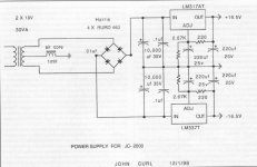
1) The authors unit came without a power supply and a schematic for a replacement using LM337/LM317 is presented. The circuit was drawn by John Curl so it certainly will fit the JC-2/ML-1, it uses no hard to source parts and should be fairly easy to build. (I can post the schematic).
I will skip this part because I have a working PLS-151 which looks good to me.
2) The author replaced the camac connectors with some Radio Shack RCA jacks and fitted them with a rat tail file (!). (Well I can´t see the point here.
Sounds to invasive to me. Connectors from Lemo are not so hard to source. I will skip that too.)
3) He had the capitance multiplier (noise filter replaced) because it was broken. The design of this filter might have an influence on the asymmetric crosstalk of the phono stage (the layout of the mainboard too, but this cannot be easily changed).
Now to the circuit:
4) The cap in the feedback loop of the line module goes out (replaced by wire). As it seems in later incarnations of the JC-2/ML-1 this has been already done - see earlier linestage picture and the later model (mine).
5) The components of the RIAA network are replaced for better accuracy. Here again later models have different phono boards so this might not be required. (BTW a test in AUDIO shows approx. +- 0.25 dB which is not that bad but of course +- 0.1 dB are possible)
6a) Replaced the coupling caps (phono and line modules) with polypropylene
types (I always though that they are already but the text says they are polycarbonate)
6b) The output caps could be ommited if the power amp has caps on his inputs. The author recommends to replace the switch (the one which shortens the caps for DC coupling) with wire because it will degrade the sound. (I think if it´s ok leave it in otherwise replace it).
6c) This is the only part which makes absolutely no sense to me: The author says, if you use the output caps one should put a 3.3 KOhm resitor
in series with it. Why should one deliberately increase the output impedance to such a high value ?
7) Two ceramic caps on the copperside are to be replaced with good film types. (I´m not shure if I have those, but there are two small green caps on top, although they look more like tantalum to me).
Ok, next to come: possible cap replacements (size) and pinout of the line modules (incl. dimensions).
Attachments
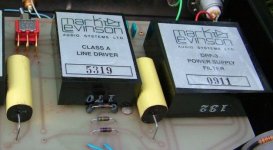
GRollins said:I've always thought it was one of the most attractive preamps made and I'd love to build something into the chassis.
Hell, even if I don't build anything into it, I'd just like to have one around to look at.
Grey
Not too long ago, I had a perfectly fine JC-2 in the house paired with a Vendetta. I believed at the time that I had died and gone to heaven. Unfortunately, the Vendetta developed a problem, and I set both of them aside while I used an integrated preamp solution, and then foolishly sold the JC-2 because I didn't fix the Vendetta and I thought ... well, I don't know what the heck I was thinking. Sigh.
(By the way, JC, I will call. Just paid for my daughter's last semester at NYU, so I have some financial breathing room.) - Pat
gk7 said:I read the Positive Feedback article yesterday and would like to summarize the points I believe are essential.
1) The authors unit came without a power supply and a schematic for a replacement using LM337/LM317 is presented. The circuit was drawn by John Curl so it certainly will fit the JC-2/ML-1, it uses no hard to source parts and should be fairly easy to build. (I can post the schematic).
I will skip this part because I have a working PLS-151 which looks good to me.
2) The author replaced the camac connectors with some Radio Shack RCA jacks and fitted them with a rat tail file (!). (Well I can´t see the point here.
Sounds to invasive to me. Connectors from Lemo are not so hard to source. I will skip that too.)
3) He had the capitance multiplier (noise filter replaced) because it was broken. The design of this filter might have an influence on the asymmetric crosstalk of the phono stage (the layout of the mainboard too, but this cannot be easily changed).
Now to the circuit:
4) The cap in the feedback loop of the line module goes out (replaced by wire). As it seems in later incarnations of the JC-2/ML-1 this has been already done - see earlier linestage picture and the later model (mine).
5) The components of the RIAA network are replaced for better accuracy. Here again later models have different phono boards so this might not be required. (BTW a test in AUDIO shows approx. +- 0.25 dB which is not that bad but of course +- 0.1 dB are possible)
6a) Replaced the coupling caps (phono and line modules) with polypropylene
types (I always though that they are already but the text says they are polycarbonate)
6b) The output caps could be ommited if the power amp has caps on his inputs. The author recommends to replace the switch (the one which shortens the caps for DC coupling) with wire because it will degrade the sound. (I think if it´s ok leave it in otherwise replace it).
6c) This is the only part which makes absolutely no sense to me: The author says, if you use the output caps one should put a 3.3 KOhm resitor
in series with it. Why should one deliberately increase the output impedance to such a high value ?
7) Two ceramic caps on the copperside are to be replaced with good film types. (I´m not shure if I have those, but there are two small green caps on top, although they look more like tantalum to me).
Ok, next to come: possible cap replacements (size) and pinout of the line modules (incl. dimensions).
Hi gk7
Very good and informative summarize.
I am looking forward to see the pinout and dimensions of the line modules.
Thanks
Some corrections to my last post
ad 1) attached the schematic
ad 4) This was an error there are 2 uF caps on the copperside of the board,
so the removal (replaced by wire) of those inside the feedback loop is valid for later serial numbers too.
ad 6c) Mr. Curl, was this 3.3 kOhm series resitor recommended by you (an if so what is the benefit of it) or is this simply a typo ?
Attachments

Thanks for the schematic!
I'm always curious to see a schematic of big John Curl")
In this case the power supply is perfectly ordinary: maybe a bit large input filtering, not seen generally. Also I don't remember that I've seen an inductor connected to the center tap of the transformer. Only thing I miss is output cap bypass...
Have fun, Hannes
I'm always curious to see a schematic of big John Curl
In this case the power supply is perfectly ordinary: maybe a bit large input filtering, not seen generally. Also I don't remember that I've seen an inductor connected to the center tap of the transformer. Only thing I miss is output cap bypass...
Have fun, Hannes
h_a said:
In this case the power supply is perfectly ordinary: maybe a bit large input filtering, not seen generally. Also I don't remember that I've seen an inductor connected to the center tap of the transformer. Only thing I miss is output cap bypass...
Well "odinary", I think it´s intended as a DIY replacement and the inductor is an interesting idea. Personally I found the LM317/337 always ok if you use enough caps around them. For the output bypass: It´s an external supply and there are bypass caps near the line mudules in the preamp case. The phono part has an extra capitance multiplier before it.
h_a said:Thanks for the schematic!
I'm always curious to see a schematic of big John Curl
In this case the power supply is perfectly ordinary: maybe a bit large input filtering, not seen generally.
The LM337 is the worst negative regulator known to mankind, when it comes to frequency response.
It's funny to hear so much fuss about large bandwidth and RF immunity, then end up with a piece of junk having essentially no PSRR or decent output impedance over 100KHz. And did anybody say NOISE?
john curl said:Syn08 is correct. The LF317 has a few problems. I hope that he can give us a better solution.
If not, then he is just blowing smoke!
To me, it is a dissapointment to see a power supply like this in a product made by JC. I am sure you can yourself figure out a decent solution for a decent power supply.
You bitch and moan about opamps not being up to your expectations, you discuss about finesses in designing the power supply, about the audibility of the power cords and filter caps, about the speed of the rectifying bridge, then you end up with a crappy stock regulator in what is supposed to be a high end product.
Though, if you need guidance in designing a decent power supply, I'm sure lots of people around may help (including myself).
The essence of this power supply schematic is right out of the National Semiconductor handbook. The 'improvements' to it precede the IC's, being high speed diodes and a choke in the center tap.
This is an easily buildable power supply by amateurs, it is not a professional design, although it does look a lot like what I normally use for my own preamps.
It is designed to replace the ORIGINAL Mark Levinson supply which was a 200ma Semiconductor Circuits module with an output of +15/-15V. This supply is somewhat better than that.
It is NOT my best however, and I don't publish my BEST schematics.
Because of the relatively limited voltage available, it is perhaps not optimum to add an additional cap multiplier pair for just the driver stage. It is what I normally use, but then, I start with +/- 30V or so.
Syno8 had his chance to give a better solution. He didn't, so I think we know where he is coming from.
syn08 said:
To me, it is a dissapointment to see a power supply like this in a product made by JC. I am sure you can yourself figure out a decent solution for a decent power supply.
To repeat it for those who get easily disappointed: It's a replacement power supply if the original is missing. (BTW while I'm writing this I'm listening to Bruckners 8th and I can tell you the JC-2 is one of the finest electronic products ever made.)
You bitch and moan about opamps not being up to your expectations, you discuss about finesses in designing the power supply, about the audibility of the power cords and filter caps, about the speed of the rectifying bridge, then you end up with a crappy stock regulator in what is supposed to be a high end product.
Have you ever attended a live classical concert and then listened to a recording of the same artists at home and asked yourself why it's harder to differentiate between the first and second violin at home ? It's about music you know.
Though, if you need guidance in designing a decent power supply, I'm sure lots of people around may help (including myself).
I would rather question why this inductor is to ground istead of having one in the plus and minus line. To quote Saint Exupery: "Perfection is achieved, not when there is nothing more to add, but when there is nothing left to take away."
syn08 said:
To me, it is a dissapointment to see a power supply like this in a product made by JC. I am sure you can yourself figure out a decent solution for a decent power supply.
You bitch and moan about opamps not being up to your expectations, you discuss about finesses in designing the power supply, about the audibility of the power cords and filter caps, about the speed of the rectifying bridge, then you end up with a crappy stock regulator in what is supposed to be a high end product.
Though, if you need guidance in designing a decent power supply, I'm sure lots of people around may help (including myself).
To repeat it for those who get easily disappointed: IHave you ever attended a live classical concert and then listened to a recording of the same artists at home and asked yourself why it's harder to differentiate between the first and second violin at home ? It's about music you know. It's a replacement power supply if the original is missing. (BTW while I'm writing this I'm listening to Bruckners 8th and I can tell you the JC-2 is one of the finest electronic products ever made.)
GK7 --
Ah - Bruckner 8th. Wonderful music, and you are so fortunate to live in Vienna. I have been there several times and love it. Both the concerts and the Huerigers are fabulous I might have a chance to be back in April -- I hope so!!!
Look at the BlowTorch thread beginning with about post 13644. John C. talks a little about the purpose of that inductor along with some other power supply/grounding issues.
Phil
Ah - Bruckner 8th. Wonderful music, and you are so fortunate to live in Vienna. I have been there several times and love it. Both the concerts and the Huerigers are fabulous
I might have a chance to be back in April -- I hope so!!!Look at the BlowTorch thread beginning with about post 13644. John C. talks a little about the purpose of that inductor along with some other power supply/grounding issues.
Phil
john curl said:
Syno8 had his chance to give a better solution. He didn't, so I think we know where he is coming from.
Indeed, I don't have a cheaper solution, but I thought JC does not do cheap stuff
. Otherwise, here's a better solution: a Jung regulator Opamp and a tranny plus some passive stuff.Last time I've seen a LM337 was in a $150 NAD phono stage. Performance was accordingly
but you get what you pay for. My expectations from a ML or JC preamp were completely different, at least after looking at the price tag.john curl said:The choke in the center tap is to keep the transformer capacitance induced high frequency garbage from getting into the ground of the preamp itself.
From the schematic it looks like the center tap (via choke) is only grounded to the chassis while the power supply ground is floating (there are some different symbols in schematics used in the US and Europe).
And this 3.3 kOhm series resitor for the output cap still makes no sense to me... please explain
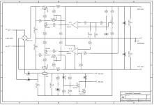
and for those who think the power supply is to simple, here is something cooked "a la Walt Jung" (stolen (whith minor modifications) from his book OpAmp applications).
Attachments
john curl said:My FREE stuff is CHEAP STUFF!
And you are not afraid to associate the horrible sound of that PS with your name?
- Home
- Source & Line
- Analog Line Level
- Need to build JC 2 preamp