5.6mA seems rather low to me, this is 1/3 of the "V" parts I use. I would not
cheap out on these parts and order them form Spencer ("BL" grade), as long as
he still has 2SJ74 available, and ask for the highest Idss matched quads he
can offer (should be around 10mA or so).
thank you Georg, I will follow your suggestion
I can confirm that the "-4dB" setting (this is 17dB gain from the line stage) is
stable; how much feedback you can apply to lower the gain without stability problems
I don´t know. (I would estimate that the gain has to be > 3 at least).
seems I made a mistake in my question, I meant low gain + low feedback or high gain + high feedback. But you got he point.
Ciao
Paolo
thank you John for chiming in!!
A 2SK246-2SJ103 combination would work OK for the JC-2 line stage.
I am trying to match the jfets (yes, I know that I can buy them already matched but I have some around that I would like to use), but I see that there can be a significant difference in Vgs between similar (<1%) Idss devices. In this particular application is better to closely match them for Idss or Vgs? ....or both?
Thanks,
Paolo
Thanks,
Paolo
When Vgs = 0, then you have Idss.
In other words when you select two same Idss devices and bias them to that value of current then the Vgs MUST be the same for the two devices.
If you were to bias the two devices to a lower value current, Id, then you will have a Vgs for each device. Now it is quite likely that the Vgs will not be the same for the two selected devices at this lower Id.
The Vgs follows a slope when plotted against Id.
Matching the SLOPE of the Vgs between devices is what matching jFETs is about.
Selecting a pair, or a quad, of same Idss devices is not matching, even though some Members sell devices with the "matched" description attached.
If you intend to bias your jFETs at a different current value from the Idss, then you should be matching the slope of Vgs vs Id, if the circuit requires similar parameters for designed performance.
Georg, I have seen in your last version that you used a trimmer between the bases of the output transistor in order to set the offset. Is this the best solution? I am asking because I have seen somewhere that a trimmer in place of R2 has been used. Basically I agree with your solution, if a matched quad of jfets is used.
pidigi, don´t worry, matching for Idss is sufficient here. What Andrew says is that for a "real" matched pair you would need to match them with a curve tracer. True, but not
feasible to match almost unavailable parts with a curve tracer you don´t have.
Offset adjustment: Of course there are several methods to accomplish this. The way
I did it was "borrowed" from the ML-2 schematic and on a total of five modules built (I made three and another member here two with my remaining boards) it worked perfectly.
If you do not need to keep the original module dimensions (like I had to, because
it was a replacement module for an existing ML-1 preamplifier) you might use
a servo instead of a manual offset adjustment. And you might (or should, actually) remove the cap in the feedback loop (see http://www.diyaudio.com/forums/solid-state/10160-need-build-jc-2-preamp.html#post1734409 ), and remove R6 (which will not be needed anymore in this case).
Finally cap multipliers like outlined for the phono stage would be a worthwhile addition...
Thank you Georg!
I understand that the "perfect match" is when the slopes are overlapping, what I am not sure is whether the slopes can be considered overlapping when Idss and Vt are the same. I think so, at least for the same jfet part number.
I will try now with your offset adjustment solution, maybe in the future I will think about a servo.
I will leave out the feedback capacitor and also the output cap (my amp is already ac coupled). Regarding the feedback resistors, I am going to use the value of the "zero" position. But since I don't need all the gain that the circuit can deliver, I am wondering if there is any way to lower the gain without increasing the feedback.
Ciao!
Paolo
I don't need a curve tracer. I don't have one................
feasible to match almost unavailable parts with a curve tracer you don´t have.
..........
I and Anatech and Cordell and Fritz and other Members have posted many times showing differential testing jigs that compare DUT & REF.
Last edited:
By the way, if R6 can be removed, can I also remove C3?
No.
Hi guys,
First I would like to say that this is my favorite forum, which I've read and learned a lot. The reason I have not written and shared many thoughts because my English is not good and my writing is bad too. Even at this moment I use google translate. Anyway ...
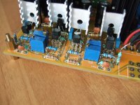
I can not stay silent because I am very excited. After reading about JC2 I decided to buy a kit from ebay mainly because of the ability to use the PCB. The kit comes with good quality parts with 2sk246/2sy103 jfet BL grade from about 10mA Idss.
After reading the advice that Mr. Curl gave us, I decided to stick as close as possible to the original scheme. As far as allowing me the parts that I have in stock.
I listened music mainly with two combinations. The first one was
2sk246/2sy103 at 6mA, 2N4401/03 at 37mA, 240 Ohm load resistantse, 113 Ohm at Potentiometer between Jfets, R33 - 2K, R34+VR5=4.53K and without C18 feedback cap.
The second one was
j113/j175 at 13mA, 2n4401/03 at 37mA, 124 Ohm load resistance, 62 Ohm at Potentiometer between Jfets, R33- 2K, R34+VR5=21k and with C18 feedback cap installed (in my case 2.2uF, I have not 2.0uF on hand).
Now the sound ...
With the first combination the sound was amazing with almost everything I love. I say almost everything because I noticed a few minor weaknesses. The first of which was in the low frequencies. After a heavy drum or bass guitar there are pulsation with extra low frequencies that can not be played from my speakers but the pulsation of the whole picture was there for less than a second. Another thing I noticed was the voice and the piano. The voice is very little back and the piano was a little dull.
The sound with the second combination is much easier to explain. It is like the first combination but without weakness. Stunning sound, very musical. The voice is right in the room. The piano is as it should be. That's why I'm so excited and decided to share it with you.
Best regards
First I would like to say that this is my favorite forum, which I've read and learned a lot. The reason I have not written and shared many thoughts because my English is not good and my writing is bad too. Even at this moment I use google translate. Anyway ...
I can not stay silent because I am very excited. After reading about JC2 I decided to buy a kit from ebay mainly because of the ability to use the PCB. The kit comes with good quality parts with 2sk246/2sy103 jfet BL grade from about 10mA Idss.
After reading the advice that Mr. Curl gave us, I decided to stick as close as possible to the original scheme. As far as allowing me the parts that I have in stock.
I listened music mainly with two combinations. The first one was
2sk246/2sy103 at 6mA, 2N4401/03 at 37mA, 240 Ohm load resistantse, 113 Ohm at Potentiometer between Jfets, R33 - 2K, R34+VR5=4.53K and without C18 feedback cap.
The second one was
j113/j175 at 13mA, 2n4401/03 at 37mA, 124 Ohm load resistance, 62 Ohm at Potentiometer between Jfets, R33- 2K, R34+VR5=21k and with C18 feedback cap installed (in my case 2.2uF, I have not 2.0uF on hand).
Now the sound ...
With the first combination the sound was amazing with almost everything I love. I say almost everything because I noticed a few minor weaknesses. The first of which was in the low frequencies. After a heavy drum or bass guitar there are pulsation with extra low frequencies that can not be played from my speakers but the pulsation of the whole picture was there for less than a second. Another thing I noticed was the voice and the piano. The voice is very little back and the piano was a little dull.
The sound with the second combination is much easier to explain. It is like the first combination but without weakness. Stunning sound, very musical. The voice is right in the room. The piano is as it should be. That's why I'm so excited and decided to share it with you.
Best regards
Attachments
Ivo, your test is interesting. The difference between to two is that the 2sk246/j103 combination has too low of working current and too low Gm, to give adequate low Z drive to the second stage. The open loop gains 'might' be similar, but the distortion generation by the second stage will be different between the two gain modules.
I´m somewhat confused by your part numbers, which schematic are you actually referring to ? 2.2uF (or 2uF) feedback cap ? You mean the DC blocking output cap ?
Georg, I am not mean DC blocking cap at output C19. I mean the feedback cap C18 refering schematic below. My ampifier already have DC blocking cap at input so I generaly not use the output capacitor at preamp.
About the noise I got it, but I'm not sure whether this is due to the parts or grounding problem.
Attachments

- Home
- Source & Line
- Analog Line Level
- Need to build JC 2 preamp