PeteMcK said:re:'don't assume you have to tune to Fs'',
Yep, most lit. I've seen makes that assumption,
any comments on tuning lower than Fs?
A good and pretty accurate guideline is to base the tuning frequency on the driver's Qts. If Qts is at or very near 0.4 (including effects on Qes and Qts of added series resistance), the system tuning should be pretty much equal to the driver's Qts. If Qts is higher than 0.4, the tuning frequency should be several Hz or more lower than Fs, and of course, the converse applies if Qts is lower than 0.4. Each driver and TL is different, of course, and you can't tell exactly what the best combination might be without good modeling software.
I don't want to rain on your parade here, but itterative modelling is not actually required to hit a specific alignment with a specific driver. Personally, I design a TL (or a reverse taper horn, or an MLTL / ML QWR etc etc etc), using my own design routine and then put it through Martin's exellent worksheets to provide you guys (or whoever) with an appropriate set of graphs.
Vas, Qt & Fs dominate TL design, just as they do with any other enclosure. There are of course many different alignments & Fp will naturally depend on the driver specs. and what you wish to achieve. Remember though, a TL proper is a line damped to ~aperiodic levels, with the object of providing the flattest possible impedance. That (the electrical TL) is where it gets its name from. Major LF output is not what they are about. Quite the reverse, most of the time.
Vas, Qt & Fs dominate TL design, just as they do with any other enclosure. There are of course many different alignments & Fp will naturally depend on the driver specs. and what you wish to achieve. Remember though, a TL proper is a line damped to ~aperiodic levels, with the object of providing the flattest possible impedance. That (the electrical TL) is where it gets its name from. Major LF output is not what they are about. Quite the reverse, most of the time.
I presume you are referring to me when you mention "raining on my parade"? Clearly we have different opinions on what constitues a "proper" TL and different methods on how to go about designing one, not to mention goals. When a TL ends up with an ~aperiodic response as you apparently prefer, much of the information between 100 Hz and 40 Hz will be attenuated at the expense of having a better response and lower frequencies where very little information exists in most forms of music. And, a maximally flat impedance is way over-rated unless one is dealing with low-powered or/and high-output impedance tubed power amps.
Scottmoose said:I don't want to rain on your parade here, but itterative modelling is not actually required to hit a specific alignment with a specific driver. Personally, I design a TL (or a reverse taper horn, or an MLTL / ML QWR etc etc etc), using my own design routineand then put it through Martin's exellent worksheets to provide you guys (or whoever) with an appropriate set of graphs.
Vas, Qt & Fs dominate TL design, just as they do with any other enclosure. There are of course many different alignments & Fp will naturally depend on the driver specs. and what you wish to achieve. Remember though, a TL proper is a line damped to ~aperiodic levels, with the object of providing the flattest possible impedance. That (the electrical TL) is where it gets its name from. Major LF output is not what they are about. Quite the reverse, most of the time.
Yes, I was speaking with you in the first paragraph. The second was a generalised statement.
No, we don't necessarily have different preferences or goals, although our methods clearly differ. However, FYI, an acoustic transmission line by definition is a line damped to ~aperiodic levels (and technically, it should be untapered too) with the principle object of providing the flattest possible impedance, making it the mythical 'perfect load.' I'm simply stating fact here, nothing else.
Naturally, a genuine TL has it's advantages and disadvantages, like all speakers. The vast majority of cabinets that are called TLs in fact fall somewhere between a TL and a QWR, and are in many ways closer to Olney's Acoustical Labyrinth, first seen in 1937, than a pure TL per se. Even Bailey's original 'Transmission Line' cabinet that spawned the Radford & later, the IMF designs of the late 1960s - early 1970s was a semi-resonant line (in direct contravention of his own 'non-resonant' subtitle ). The real trick of course is to use them to support some of the LF region while minimising passband harmonic ripple as far as possible.
Anyway, that is one of the aspects I was refering to when I commented upon there being 'many different alignments.' These are no different to a pure TL, and itterative modelling in software is not an automatic requirement to hit a chosen alignment. That's not to suggest it isn't a perfectly valid design method (it is), but that it is erroneous to say that you cannot establish your optimal alignment without it. I've been one of Martin's supporters for some years, and I wouldn't be without his MathCAD worksheets, but that doesn't mean I design a box by trial & error in his software. As I mentioned above, I design a cabinet first, to meet the specified criteria, and then run it through MathCAD.
No, we don't necessarily have different preferences or goals, although our methods clearly differ. However, FYI, an acoustic transmission line by definition is a line damped to ~aperiodic levels (and technically, it should be untapered too) with the principle object of providing the flattest possible impedance, making it the mythical 'perfect load.' I'm simply stating fact here, nothing else.
Naturally, a genuine TL has it's advantages and disadvantages, like all speakers. The vast majority of cabinets that are called TLs in fact fall somewhere between a TL and a QWR, and are in many ways closer to Olney's Acoustical Labyrinth, first seen in 1937, than a pure TL per se. Even Bailey's original 'Transmission Line' cabinet that spawned the Radford & later, the IMF designs of the late 1960s - early 1970s was a semi-resonant line (in direct contravention of his own 'non-resonant' subtitle
). The real trick of course is to use them to support some of the LF region while minimising passband harmonic ripple as far as possible. Anyway, that is one of the aspects I was refering to when I commented upon there being 'many different alignments.' These are no different to a pure TL, and itterative modelling in software is not an automatic requirement to hit a chosen alignment. That's not to suggest it isn't a perfectly valid design method (it is), but that it is erroneous to say that you cannot establish your optimal alignment without it. I've been one of Martin's supporters for some years, and I wouldn't be without his MathCAD worksheets, but that doesn't mean I design a box by trial & error in his software. As I mentioned above, I design a cabinet first, to meet the specified criteria, and then run it through MathCAD.
Actually I don't use Martin's worksheets in a "trial and error" process as if I have no idea of what to do and just plug in data until something good happens, but I also don't design a TL first some other way then just check it with his worksheets. My goal, regardless of the "type" of TL is to obtain a flat response (not more than 1 dB down) to 40 Hz, have small-amplitude ripples above the knee (+/- 0.5 dB if possible, not more than +/- 1 dB) and a terminus or port air velocity of not more than 1.5% the speed of sound when the system is generating 87 dB or more SPL and with an input of 2.83 volts. Once I achieve the flat response to 40 Hz, F3 is whatever it is. I can predict quickly before modeling what the optimum system tuning frequency needs to be, then my modeling is limited mostly to what type of TL, optimum driver and port/terminus locations, how much stuffing is needed and how big the cabinet must be to give me these desired results. I can't imagine how one could design a TL without using either Martin's worksheets or something similar, and have much confidence at all that the actual performance would be as expected if even good. For instance, it's one thing to say, "for optimum performance, locate the driver so it's 20% of the line's length from the closed end", when in fact, the optimum location could easily be somewhere between 15% and 25%. How could you possibly determine that location without modeling? As far as personal preferences go, I prefer a tapered TL when it's appropriate (and a taper ratio of at least 10:1), but I also like and have often used an ML-TL because of it's inherently simpler and easier to build. I've modeled ML-TQWTs but haven't built any. The very last type of alignment I'd ever use for a full-range system is the "genuine" type you define. If it's stuffed for good bass response, there will likely be large dips and peaks in the response at the line's harmonics. If it's stuffed enough to get rid of those peaks, then F3 will be quite high or the box will be really big.
Scottmoose said:Yes, I was speaking with you in the first paragraph. The second was a generalised statement.
No, we don't necessarily have different preferences or goals, although our methods clearly differ. However, FYI, an acoustic transmission line by definition is a line damped to ~aperiodic levels (and technically, it should be untapered too) with the principle object of providing the flattest possible impedance, making it the mythical 'perfect load.' I'm simply stating fact here, nothing else.
Naturally, a genuine TL has it's advantages and disadvantages, like all speakers. The vast majority of cabinets that are called TLs in fact fall somewhere between a TL and a QWR, and are in many ways closer to Olney's Acoustical Labyrinth, first seen in 1937, than a pure TL per se. Even Bailey's original 'Transmission Line' cabinet that spawned the Radford & later, the IMF designs of the late 1960s - early 1970s was a semi-resonant line (in direct contravention of his own 'non-resonant' subtitle
Anyway, that is one of the aspects I was refering to when I commented upon there being 'many different alignments.' These are no different to a pure TL, and itterative modelling in software is not an automatic requirement to hit a chosen alignment. That's not to suggest it isn't a perfectly valid design method (it is), but that it is erroneous to say that you cannot establish your optimal alignment without it. I've been one of Martin's supporters for some years, and I wouldn't be without his MathCAD worksheets, but that doesn't mean I design a box by trial & error in his software. As I mentioned above, I design a cabinet first, to meet the specified criteria, and then run it through MathCAD.
A few general thoughts, in reverse order
1/ A genuine TL is a genuine TL. As I said before, I'm simply stating what it is. Nobody is advocating it in every circumstance & if they did, it'd be time to call the nice men in white coats. There are some cases where it is appropriate, some where it is not. That is dependant upon the design goal / objectives. You design to meet those.
Big is good generally though -within reason, the bigger the better. It's one less thing to worry about, & TLs & their variations generally need quite a large Vp, not so much in terms of FR, but to prevent the upper-bass / lower midrange being 'strangled' (for want of a better phrase) by lack of pipe volume. Unfortunately, that's not something that tends to show up on a computer model. Here's a quick example I knocked out a couple of years back to illustrate this point. Don't worry if you don't like the F3; it doesn't matter. Not a whole lot of difference in the FR, right? Bit more gain in the lower, but not a vast amount. That's mirrored in the other plots. The lower box has (wait for it) around 35% more Vp than the upper. Damping removed, the basic responses still don't change a whole lot compared one against the other. Sonically however, it's transformed, with far more midbass slam & clarity than the smaller box.
2/ For the sake of interest, an ML TQWT is actually a mass-loaded conical horn. TQWT has only in recent years been adopted for an expanding line. Not sure how / why, although Weems may be the responsible party... Anyway, traditionally, TQWT was in fact a reverse taper horn, i.e. a line that narrows toward the terminus. I've built a few (in the modern parlance), designed far more. I quite like them; they certainly have their uses.
3/ A reverse / negative taper line (or trad. TQWT) is inherently mass-loaded. However, you have to be careful with extreme taper ratios as distortion starts to increase beyond what I consider to be acceptable. 6:1 is my limit for LF duties & I generally prefer not to go that far -midrange lines are a different matter of course, as they are invariably fully damped aperiodic TLs.
4/ MLTLs / ML QWRs = another cabinet type I like. I was trying to put my archived designs into some semblence of order a couple of weeks ago (I use a tame black hole for a filing system on the HDD) & found roughly 600 different cabinets of this type I've done over the past 5 years or so, either as requests or quick checks for an interesting driver. A good option for vented alignments generally IMO.
5/ How to determine driver offset without modelling? Physics. It depends on the design requirements of course I normally use a driver position I learned from a friend who's been designing these things since the 1960s that varies with length / CSA for minimal phase distortion, along with supressing unwanted line harmonics etc. of course.
6/ Related to the above, yes indeed, they can be designed without Martin's software (assuming you know how to do it) or similar. That is not saying anything against it, or Martin: his worksheets are a Godsend to me and for many others as far as I'm concerned for many reasons. I especially value the 2nd half of the sheets with the in-room calculations etc.
7/ No disagreement from me WRT your design goals, assuming you're accounting for room-gain etc. at flat to 40 generally is going to cause problems in most spaces. TBH, I also generally go max-flat for DIY MLTL requests, and leave the end user to adjust from there to suit themselves via vent tuning. Tapered lines = not so easy for people to adjust as you don't have the flexibility of the vent, so my take is generally to provide a damped design with minimal passband ripple (which usually blends well into room-lift) but which will provide more gain if desired, when some of the damping is removed from the last 10 - 12in or so, while still preserving a reasonable degree of harmonic attenuation.
1/ A genuine TL is a genuine TL. As I said before, I'm simply stating what it is. Nobody is advocating it in every circumstance & if they did, it'd be time to call the nice men in white coats.
There are some cases where it is appropriate, some where it is not. That is dependant upon the design goal / objectives. You design to meet those. Big is good generally though -within reason, the bigger the better. It's one less thing to worry about, & TLs & their variations generally need quite a large Vp, not so much in terms of FR, but to prevent the upper-bass / lower midrange being 'strangled' (for want of a better phrase) by lack of pipe volume. Unfortunately, that's not something that tends to show up on a computer model. Here's a quick example I knocked out a couple of years back to illustrate this point. Don't worry if you don't like the F3; it doesn't matter. Not a whole lot of difference in the FR, right? Bit more gain in the lower, but not a vast amount. That's mirrored in the other plots. The lower box has (wait for it) around 35% more Vp than the upper. Damping removed, the basic responses still don't change a whole lot compared one against the other. Sonically however, it's transformed, with far more midbass slam & clarity than the smaller box.
2/ For the sake of interest, an ML TQWT is actually a mass-loaded conical horn. TQWT has only in recent years been adopted for an expanding line. Not sure how / why, although Weems may be the responsible party... Anyway, traditionally, TQWT was in fact a reverse taper horn, i.e. a line that narrows toward the terminus. I've built a few (in the modern parlance), designed far more. I quite like them; they certainly have their uses.
3/ A reverse / negative taper line (or trad. TQWT) is inherently mass-loaded. However, you have to be careful with extreme taper ratios as distortion starts to increase beyond what I consider to be acceptable. 6:1 is my limit for LF duties & I generally prefer not to go that far -midrange lines are a different matter of course, as they are invariably fully damped aperiodic TLs.
4/ MLTLs / ML QWRs = another cabinet type I like. I was trying to put my archived designs into some semblence of order a couple of weeks ago (I use a tame black hole for a filing system on the HDD) & found roughly 600 different cabinets of this type I've done over the past 5 years or so, either as requests or quick checks for an interesting driver. A good option for vented alignments generally IMO.
5/ How to determine driver offset without modelling? Physics.
It depends on the design requirements of course I normally use a driver position I learned from a friend who's been designing these things since the 1960s that varies with length / CSA for minimal phase distortion, along with supressing unwanted line harmonics etc. of course. 6/ Related to the above, yes indeed, they can be designed without Martin's software (assuming you know how to do it) or similar. That is not saying anything against it, or Martin: his worksheets are a Godsend to me and for many others as far as I'm concerned for many reasons. I especially value the 2nd half of the sheets with the in-room calculations etc.
7/ No disagreement from me WRT your design goals, assuming you're accounting for room-gain etc. at flat to 40 generally is going to cause problems in most spaces. TBH, I also generally go max-flat for DIY MLTL requests, and leave the end user to adjust from there to suit themselves via vent tuning. Tapered lines = not so easy for people to adjust as you don't have the flexibility of the vent, so my take is generally to provide a damped design with minimal passband ripple (which usually blends well into room-lift) but which will provide more gain if desired, when some of the damping is removed from the last 10 - 12in or so, while still preserving a reasonable degree of harmonic attenuation.
Attachments
I put that in when I added the second sheet with the cabinet.. if, for whatever reason, you want a larger or smaller cross section than the allignment tables give, it will calc the cab dimensions for you.PeteMcK said:can you explain/comment on the use of the 'Correction on the line cross section' number?
on the design process: I found Martin's allignment tables an excelent starting point, I have made a few very nice designs (e.g. the 2 desktop TL's, and the Hans floorstanding 2way) where all I had to do in the mathcad sheets was to optimise the stuffing and maybe some rounding off to easy numbers and the TL was ready. so what I now usually do is start with this excel sheet and more or less only verify with mathcad.
It's a nice extra touch that.
Martin's tables really are very good indeed & corrolate very closely with the handful of other other effective methods of sizing. For me, the main value of his work in this field has been to establish / illustrate the relationship of taper to resonant frequency in a much more detailed way than had previously been done. This has been particularly significant for negative taper lines. Augspurger went some way toward this at roughly the same time as Martin, but without as much detail, although the two papers tend to complement each other in some respects. Theoretically, it should have been possible to get close before with a bit of creative thinking WRT the resonant behaviour of cones, but AFAIK, no studies were published forwarding the idea let alone confirming it, and it certainly didn't occur to me until fairly recently -several years after I'd read Martin's work.
Martin's tables really are very good indeed & corrolate very closely with the handful of other other effective methods of sizing. For me, the main value of his work in this field has been to establish / illustrate the relationship of taper to resonant frequency in a much more detailed way than had previously been done. This has been particularly significant for negative taper lines. Augspurger went some way toward this at roughly the same time as Martin, but without as much detail, although the two papers tend to complement each other in some respects. Theoretically, it should have been possible to get close before with a bit of creative thinking WRT the resonant behaviour of cones, but AFAIK, no studies were published forwarding the idea let alone confirming it, and it certainly didn't occur to me until fairly recently -several years after I'd read Martin's work.
check, for example the CSS FR125 I have used in a TL tuned below 50Hz (fs=70Hz).pkitt said:A good and pretty accurate guideline is to base the tuning frequency on the driver's Qts. If Qts is at or very near 0.4 (including effects on Qes and Qts of added series resistance), the system tuning should be pretty much equal to the driver's Qts. If Qts is higher than 0.4, the tuning frequency should be several Hz or more lower than Fs, and of course, the converse applies if Qts is lower than 0.4. Each driver and TL is different, of course, and you can't tell exactly what the best combination might be without good modeling software.PeteMcK said:re:'don't assume you have to tune to Fs'',
Yep, most lit. I've seen makes that assumption,
any comments on tuning lower than Fs?
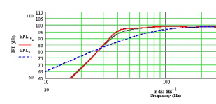
on the "flat to 40" point, and tuning to taste, in the same FR125 design, I have adjusted the low end output by adding stuffing in the last part of the line, see the attached graph (red line is base design, black with additional stuffing)
In the spreadsheet I could modify the recommentation based om Qt..
Attachments
You just weren't looking in the right places.
Ain't that the truth Greg.
You pointing me in that direction is one of the (many) things I owe you thanks for. check, for example the CSS FR125 I have used in a TL tuned below 50Hz (fs=70Hz).
on the "flat to 40" point, and tuning to taste, in the same FR125 design, I have adjusted the low end output by adding stuffing in the last part of the line, see the attached graph (red line is base design, black with additional stuffing)
That's nice. Out of interest, do you mind if I ask what driver specs & power input you used? I assume, looking at the IB curve on your graph, & the factory specs for the current FR125SR, that it's for two drivers, paralleled, with about 3w input, as the IB response is far above the 85.5db 1m/1w sensitivity of a single unit, and the basic response curve is somewhat different as well. Or was it using the older FR125S model with a different power-input?
Best
Scott
I used the factory specs for the FR125SR, and had the power so far up that the cone excursion would hit Xmax at 40HzScottmoose said:.....what driver specs & power input you used?
Scottmoose said:b/ the 125 doesn't have progressive rate suspension AFAIK, so you're going to be bouncing the VC off the back-plate if you go much further
With the FR125 this is an often under-considered issue. We have moved to 4.5-7 litre aperiodic boxes as we feel this gets the best out of these drivers.
dave
Yeah, when you initially commented on the original FR125S's severely limited gap between Xmax-Xmech that apparently defines the XBL^2 motor's character I was rather surprised. When I finally got to tune some in an existing 40-1354 MLTL last year I was even more so since I couldn't hear any non-linear distortion between high excursion and bottoming the VC, making it kind of hard to tune by ear, so ultimately tuned in a peak at its ~35 Hz Fb to handle DSOTM and Brian Bromberg's bass sub harmonics, the only two recordings that we had trouble with.
Fortunately, the two I have are well constructed and didn't get audibly damaged after several collisions, but XBL^2 is a 'double edged sword' that could explain why I've heard about more of these type sub drivers being damaged than the more traditional units. Nothing like a sub in audible distress to cause a beeline to either the volume control and/or bass boost knob.
GM
Blast. What happened to the 2nd paragraph of my last post? The graph's still there. Ghost in the machine, that's what it is. Anyway, near as I can remember, the gist of it went something like this:
'I got similar results from a cab. design I did shortly after the FR125S was upgraded to SR standard; the response plot attached (now attached above ) is from that box, with the wick turned up so it's hitting Xmax at Fb. That's not to say I'd recommend this alignment per se. a/ as we're at Xmax at these SPLs, there's no dynamic headroom left (although at more modest levels, in a small room, it should be pretty decent for an FR driver based system), b/ the 125 doesn't have progressive rate suspension AFAIK, so you're going to be bouncing the VC off the back-plate if you go much further, and c/ a max-flat alignment is not in itself usually a good idea in-room; I use it for DIY boxes on the understanding that the end user will tweak things to suit their own system / room / preferences.'
Anyway, near as I can remember, the gist of it went something like this:'I got similar results from a cab. design I did shortly after the FR125S was upgraded to SR standard; the response plot attached (now attached above
) is from that box, with the wick turned up so it's hitting Xmax at Fb. That's not to say I'd recommend this alignment per se. a/ as we're at Xmax at these SPLs, there's no dynamic headroom left (although at more modest levels, in a small room, it should be pretty decent for an FR driver based system), b/ the 125 doesn't have progressive rate suspension AFAIK, so you're going to be bouncing the VC off the back-plate if you go much further, and c/ a max-flat alignment is not in itself usually a good idea in-room; I use it for DIY boxes on the understanding that the end user will tweak things to suit their own system / room / preferences.'Sorry, to disturb the lively discussion, but how does some one get a hold of Martin's Worksheets these days?
I used to have them when they were free. It looks like at some point he charged for them, now you can't get them from his website at all?
Only program I've gotten to model TL's sucessfully is DosBox and dirty little Vista doesn't want to run it in fullscreen, so I can't see the graphs. Also, it's probably not as accurate as MJK's worksheets, I assume.
I used to have them when they were free. It looks like at some point he charged for them, now you can't get them from his website at all?
Only program I've gotten to model TL's sucessfully is DosBox and dirty little Vista
doesn't want to run it in fullscreen, so I can't see the graphs. Also, it's probably not as accurate as MJK's worksheets, I assume.Well, to my way of thinking, now that none are available from him, the folks who still have the original freeware should be able to share them. For that matter, they should have always been able to, same as with any 'demo' program.
Regardless, AkAbak can do them AFAIK and except for stuffing effects, various style MLTLs, offset drivers, etc., even 'tapped' variants can now be simmed in HornResp, though the vent can only be at the (open) end. If you're metric challenged like me, a spreadsheet to do the various calculations for ease of inputting is recommended. (no, I haven't done one).
GM
- Status
- This old topic is closed. If you want to reopen this topic, contact a moderator using the "Report Post" button.
- Home
- Loudspeakers
- Multi-Way
- need help with TL calculations