there is only one schematic.
A quick mental arithmetic on the 3 PINs gives me about 500mV on +IN and 500mV on -IN and this results in about 1500mV on OUT.
That confirms all these PINs are tied to -ve rail.
Well I've checked that I'm looking at the schematic posted.
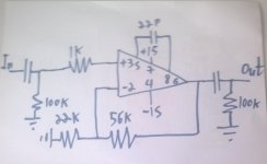
The +In connects to ground through a series combination of 1k and 100k, the junction between the two has the input cap feeding in - how do you see 500mV on +In?
The -In connects into the feedback voltage divider, nothing too weird there?
Shurely shome mishtake!
The input bias current times the input resistance to ground gives the voltage across the input resistors. I would expect that voltage to be somewhere between 100mVdc and 500mVdc.
An opamp does what is required with the output to make the voltage on the -IN PIN equal to the voltage on the +IN PIN. If you accept that, then the -IN PIN voltage must also be very close to the +IN PIN.
Working from that you can then determine the approximate output voltage using the feedback resistors and a guess at the -IN bias current.
All three PINs will have voltages close to the -ve rail.
That all assumes that the opamp does not mind having all those PINs near -ve rail.
So I come back to my question. Does the 5534 survive that operating condition?
Last edited:
Don't give up, here are some ideas how I would start:
- Use 2x 9V batteries (one for pin7 positive voltage, one for pin 4 negative voltage) for experimenting
- Use IC sockets
- Get some cheap opamps (e.g. uA741 that is pin compatible). If that works, just replace the opamp in the socket
- Don't forget the pin numbering is seen from the top, not from the bottom
- Buy the NE5534 from the nearby parts shop, not from eBay. It is dirt cheap anyway...
The input bias current.......
So I come back to my question. Does the 5534 survive that operating condition?
Yes, my mistake, bipolar ic, those 100ks are bigger than they need to be here. The TI 5534 lists Iib as typically 500nA, but possibly as high as 2000nA, with Iio max 400nA.
Just to check, inputs feed into bases of npn diff pair, so input bias currents flowing inwards, ok. With the circuit as shown, ie power supply plain wrong, the +In transistor base is connected to 0v via that 100k resistor - not much current is going to end up flowing in that terminal at all, leaving the -In side to feed the ccs below the input diff pair - if it can.

-In has 22k to ground and 56k to Out, which will be down as low as it can get, but feeding into that 56k.
So far I can't see anything melting on account of the circuit as shown, though obviously it has melted!
The difficulty with someone with this little idea of what's what is making a reasonable guess as to what they're doing wrong of course, and to try to offer sensible advice, encouraging without being ludicrously over-optimistic. I think oshifis hits the right note.
Btw, whilst the 741 has no pin connection for compensation, the pinouts are otherwise the same, so as oshifis says, getting a circuit working with a 741 then swapping in another better opamp, including the 5534 would seem sensible. Though it's up to WhiteRhino how much stamina he has for this, a lot of folk do seem to find this stuff less fascinating than we do. I have heard it suggested that that's because they have lives, but those uttering such heresies should just be punched.....
Last edited:
I just blew up the chips ...
never mind my qeustions I have to get another opamps ..
How do you know its blown up??
jan
if some one will draw me a schematic with the ne5534 opampDon't give up,
I will try again
the ne5534 is very cheep it coast only 2 $ .
came out of them allot of smoke , i threw them to trash any way ,How do you know its blown up??
jan
if some will draw me a schematic how to use the 5543 , i will try again
came out of them allot of smoke , i threw them to trash any way ,
if some will draw me a schematic how to use the 5543 , i will try again
Drawing schematics is a bit like hard work WhiteRhino, especially for those of us like me who don't have a scanner connected.
Read my post earlier, and redraw your schematic with the two resistors added, then you should be getting something viable.
Or, take heed of oshifis's suggestion, use a pair of PP3 batteries to give twin rail supply and connect your pin 4 to the -ve rail.
I just blew up the chips ...
never mind my qeustions I have to get another opamps ..
ok I make it easier for you .
what do you think about this ?
every thing ok ?
That will work but it's not perfect. The 100K+1K and the feedback resistor (the 56K) should be equal to minimise DC offsets. The 22K should then be capacitor coupled to ground to give the opamp a gain of 1 at DC. A 10uf electroylitic is ideal for that.
But yes, it will all work as it is.
I would maybe get some different opamps as well as the 5534's. The TL071 is very decent, it's stable and good to experiment with. If you used a FET opamp the DC offset problem disappears and the small frequency compensation cap will not be needed if the layout is good. If it were needed it goes across the 56K for the TL071 and most other opamps.
Last edited:
As has been pointed out by AndrewT, (if a bit too obliquely for the slow-witted like myself to catch on to at once  ) and by Mooly, the issue of input bias current does need to be considered. As Mooly says, this is less of an issue with fet opamps like TL071.
Both inputs need to have a small current flowing into them to work. Usually these currents are of similar size, so making the dc resistance to ground, seen looking out from the input terminals the same, results in less offset away from 0v dc at the output. Which is a good thing. If this output offset voltage is low enough for whatever amp you want to connect to to be happy, then you can get rid of the output coupling capacitor.
Incidentally, it would probably be a good thing to put a 100R resistor in series with the output of the op-amp to avoid high frequency instability driving a capacitive cable or load. This is my understanding reading posts by DF96 on another current thread, and agrees with my experience, and my now hazy recollections of feedback theory and the s-plane.
Mooly's idea of putting a 10uF electrolytic in between the 22k resistor and ground should work, so that only the 56k feedback resistor is a path to ground (the output counts as that here) and make your 100k input resistor 56k instead. Connect the negative plate of the cap to ground, btw.
Alternatively, with the 56k and 22k as is, you could drop the 100k input resistor down to 18k, still high enough for cd players and the like to drive easily, and possibly slightly less noisy. With 18k to ground on your input, make the input capacitor 0u47 or 1u0 for full audio bandwidth, low enough to use a polyester cap rather than an electrolytic.
As pointed out by AndrewT earlier, the gain you'll see with 56k and 22k is (56 + 22) / 22 = 3.5
With 68k instead you'd get gain = 4.0, and with 82k instead of 56k, gain = 4.7, close enough?
) and by Mooly, the issue of input bias current does need to be considered. As Mooly says, this is less of an issue with fet opamps like TL071.Both inputs need to have a small current flowing into them to work. Usually these currents are of similar size, so making the dc resistance to ground, seen looking out from the input terminals the same, results in less offset away from 0v dc at the output. Which is a good thing. If this output offset voltage is low enough for whatever amp you want to connect to to be happy, then you can get rid of the output coupling capacitor.
Incidentally, it would probably be a good thing to put a 100R resistor in series with the output of the op-amp to avoid high frequency instability driving a capacitive cable or load. This is my understanding reading posts by DF96 on another current thread, and agrees with my experience, and my now hazy recollections of feedback theory and the s-plane.
Mooly's idea of putting a 10uF electrolytic in between the 22k resistor and ground should work, so that only the 56k feedback resistor is a path to ground (the output counts as that here) and make your 100k input resistor 56k instead. Connect the negative plate of the cap to ground, btw.
Alternatively, with the 56k and 22k as is, you could drop the 100k input resistor down to 18k, still high enough for cd players and the like to drive easily, and possibly slightly less noisy. With 18k to ground on your input, make the input capacitor 0u47 or 1u0 for full audio bandwidth, low enough to use a polyester cap rather than an electrolytic.
As pointed out by AndrewT earlier, the gain you'll see with 56k and 22k is (56 + 22) / 22 = 3.5
With 68k instead you'd get gain = 4.0, and with 82k instead of 56k, gain = 4.7, close enough?
Last edited:
Re the preamp.
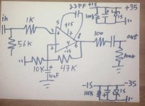
You've sussed how to get the gain where you want it, that's fine. Where you've gone wrong is that the 10uF capacitor needs to be in series with the 10k resistor, not parallel. So, for clarity, path going out from the -In terminal of the opamp is:
take the right hand fork to the 10k, passing the 47k on your left, go through the 10k, reach the +ve plate of the 10uF cap, through that to ground.
Btw, as you've drawn it, with the 10u cap bypassing the 10k resistor, you've got a very high gain amplifier, that might work quite well as as a guitar distortion unit, though with twin rail 15v supplies a bit over the top.
You need to choose a value for your input and output capacitors, I suggest 220nF or 470nF at the input, ie 0u22 or 0u47. At the output it depends totally on what you're going to drive. If the dc offset is low (measure it with a voltmeter) you maybe don't need an output cap.
Re the power supply.
A few (sadly fatal!) flaws here! Polarity of reservoir cap in -ve is wrong - wired like this it will probably explode. Think which way round the voltage is!
The zener diode, connected across the reservoir cap will draw very heavy current indeed if you feed it from what appears to be a 35v power source. It will explode too! This topology is not promising, though there are other simple solutions that will do fine.
So some more thought needed on this, can you tell me what your power source is actually going to be - that would help. In the meantime a pair of 9v PP3 batteries will do well for testing purposes.
Last edited:
I hope i understand you .
what do you think of this ?
by the way what do you think of the power suply ?
thanks
Have a look at these. Post #71,
http://www.diyaudio.com/forums/anal...ic-common-emitter-amp-help-4.html#post2089750
and this one, post #6 and #37 #62 but read it all.
http://www.diyaudio.com/forums/analog-line-level/167495-simple-stereo-gain-stage.html#post2198757
http://www.diyaudio.com/forums/analog-line-level/167495-simple-stereo-gain-stage.html#post2198757
http://www.diyaudio.com/forums/analog-line-level/167495-simple-stereo-gain-stage-4.html#post2225076
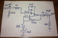
That will work OK with a split supply. You don't really need the 1K and the 47K should be 56K for best DC balance but as it's AC coupled that matters little. Make sure you measure the DC voltage across the 10uf's when it's working and fit them according to the polarity of voltage measured.
220nf and 56K will roll off low frequencies.
If you have Java try this and put say 15Hz, 56K and 220nf in.
High Pass Filter - Java Experiment
You can make the 56K much higher to say 470K if you want to avoid a large cap for the input. The downside of that is that the DC offset increases but again, AC coupled it doesn't matter so much.
The 5534 isn't a precision DC amp anyway.
High Pass Filter - Java Experiment
I think there might be a danger of going round in circles here on the preamp design. I think the OP chose 47k and 10k to give a gain of 5.7x and if he's going with AC coupled then as you say, minor offsets are hopefully not a problem.
Re the input cap and resistor. I make the 3dB corner frequency of the resulting high pass filter about 12Hz - low enough surely? Or have I forgotten more than I thought I had?
The thing that I think still needs some work is the power supply. If the AC wall wart that the OP mentions is as I presume it is, ie a single 12v AC output, then he will need to use two diodes to get half wave rectification for each of the two power rails, though if he already has a bridge rectifier he can just connect to two of the diodes in it. This will mean that ripple is increased compared to a full wave scheme.
No mention has yet been made of proper smoothing and regulation of this supply and I'd say it needs it.
thanks simon , so everything ok ?
about the power supply is indeed somthing that worry's me .
the power amp (stereo reciever ) is 70's Marantz 2226
It has +- 35 DC , and I don't how to lower it to 15 + - .
i searching for the simple but safe way to do it .
I'll be glad if you show me how .
about the power supply is indeed somthing that worry's me .
the power amp (stereo reciever ) is 70's Marantz 2226
It has +- 35 DC , and I don't how to lower it to 15 + - .
i searching for the simple but safe way to do it .
I'll be glad if you show me how .
- Status
- This old topic is closed. If you want to reopen this topic, contact a moderator using the "Report Post" button.
- Home
- Source & Line
- Analog Line Level
- Need help with the NE5543N opamp