this information comes from the capacitor test and what he had to do to be able to measure the distortion.If capacitor is used for DC blocking only then there is no AC voltage across the cap... AndrewT writes about this over and over but people still can't understand this simple fact.
If capacitor is used for DC blocking only then there is no AC voltage across the cap... AndrewT writes about this over and over but people still can't understand this simple fact.
This is only the case if the cap has a much lower impedance than the rest of the circuit. In general, there IS AC across a coupling cap, it is just an impedance and forms a voltage divider with whatever comes after it.
But, and that is what Andrew means, if you make the cap very large, with respect to the load on it, the voltage divider becomes a very large ratio and the AC across the cap becomes very small. But you need to know what you are doing.
Jan
Andrew, Jan, I pretty much aware of all these. It is a matter of selecting an appropriate value capacitor for the DC blocking duty. If it is sized correctly than the distortion measured by Cyril Bateman scaled down by the voltage divider ratio is getting so small that it becomes a non-issue. I think you are replying to the wrong person")
Bateman's findings also justify the recommendation that if electrolytic cap is used for DC blocking duty it should be of much higher value than the necessary film capacitor. This just helps to scale further down intrinsically higher distortion of electrolytic capacitors by increasing the voltage divider ratio.
I think you are replying to the wrong person
Well, sorry, but you said:
If capacitor is used for DC blocking only then there is no AC voltage across the cap...
... so that what was I replied to. I cannot read minds....
Jan
Originally Posted by OlegSh
Zero D seems to refer to max permitted AC voltage across the cap which falls rapidly with frequency, reaching around 1~2VAC max at 20kHz (for 4.7~10uF caps). This is how I understood his post
Yes you understood correctly
I only posted it as a general heads up. For speaker Xovers it should be a consideration
but the mere existence, frequency range and resolution of the LM4562 data sheet PSRR and CMRR plots make it unlikely that the problem is actually the LM4562 PSRR
for line level audio I only use FET input op amps
You keep reading and believing those data sheets, jcx.
The LM4562 is just another example where the data sheet and "real world" applications don't jive.
FET input op-amps are great with their high input impedance and negligible offset, but they don't always sound the best in low gain audio applications.
You should know this as well as anybody here since you're such a proponent of the CFA TPA6120.
Even though the '4562 is a bipolar op-amp, which I might be able to eliminate all the hum and other garbage by mounting it in some type of metal enclosure, I still don't care for it's "dry and lifeless" sound that some folks find to be "neutral".
Thank goodness this thread is about the NE5532 and not the LM4562. Sorry that I "derailed" this thread by mentioning the LM4562.
Now...let's bust out the whiskey and the soldering iron and build something!
The Ebay buffer didn't work in my application.
I have finally got round to breadboarding buffers.
Application - Differential (balanced input - balanced output) buffer for Anaview Amplifier.
1 - Ebay inverting buffer - no sound used as a differential buffer.
2 - non-inverting buffer (as post 2) - works.
3 - inverting buffer (breadboarded) - no sound used as a differential buffer.
Test 3 was to prove to myself that it wasn't a fault with the ebay item.
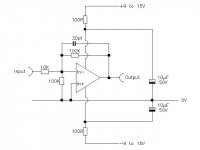
I attach the schematic of the inverting buffer (same as post 1 - didn't realise when posting that pdf only shows icon). Half circuit shown. Both halves used for (non-working) differential buffer.
I have finally got round to breadboarding buffers.
Application - Differential (balanced input - balanced output) buffer for Anaview Amplifier.
1 - Ebay inverting buffer - no sound used as a differential buffer.
2 - non-inverting buffer (as post 2) - works.
3 - inverting buffer (breadboarded) - no sound used as a differential buffer.
Test 3 was to prove to myself that it wasn't a fault with the ebay item.
I attach the schematic of the inverting buffer (same as post 1 - didn't realise when posting that pdf only shows icon). Half circuit shown. Both halves used for (non-working) differential buffer.
Attachments
opamps and circuits that emulate them are all differential input.
If you use a single ended amplifier to amplify or pass a signal you must input TWO signal leads and the amplifier reads that differential voltage between the two input wires and processes that signal.
A balanced input amplifier does exactly the same. It reads the differential voltage and processes that signal.
If your two unbalanced experiments produced no sound, then you probably forgot to connect the differential input to the two input signals.
Look at your schematic. The opamp has TWO inputs, -IN (In-) and +IN (In+).
You must connect the two input wires to these two inputs.
Last edited:
The circuit as drawn looks fine although the 100k's to ground are not needed for the inverting stage although they won't materially affect the operation. Also the inverting side has a gain of -10 compared to the non inverting buffers <1
Are the DC voltages reasonable i.e. the output being at zero volts DC ?
Are the DC voltages reasonable i.e. the output being at zero volts DC ?
Pin 1 shield of buffer input is connected to Ov ground.
The Anaview multi-pin connector has a number of black wires, all are common and also connected to ground plane & thence to metal case.
One is connected to buffer and one to shield of input connector therefore the shield is connected to buffer Ov.
I have checked continuity with DMM to confirm.
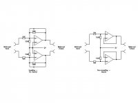
I have never seen an op-amp differential buffer schematic showing inverted configuration. I am thinking this is because it doesn't work. I am curious why.
I can soon build the non-inverting buffer on stripboard and use it in my set-up.
I only bought the Ebay buffer because it was neater on a PCB.
The Anaview multi-pin connector has a number of black wires, all are common and also connected to ground plane & thence to metal case.
One is connected to buffer and one to shield of input connector therefore the shield is connected to buffer Ov.
I have checked continuity with DMM to confirm.
I have never seen an op-amp differential buffer schematic showing inverted configuration. I am thinking this is because it doesn't work. I am curious why.
I can soon build the non-inverting buffer on stripboard and use it in my set-up.
I only bought the Ebay buffer because it was neater on a PCB.
I have never seen an op-amp differential buffer schematic showing inverted configuration. I am thinking this is because it doesn't work. I am curious why.
I haven't either. The only thing I could think of (and it doesn't compute) is that you are getting 100% cancellation somehow. Why not try unbalancing things by either lifting one of the 10k input resistors, or adding say a 4k7 across one of them and then see if you get audio.
- Status
- This old topic is closed. If you want to reopen this topic, contact a moderator using the "Report Post" button.
- Home
- Source & Line
- Analog Line Level
- NE5532 Buffer