Hi Foo,
I did not get to it today (just watched Ratatouille in the home theater/sound room/garage with my wife and it did what a good movie played on a good system should do...it made me forget about the world and go somewhere else fun for a couple of hours). Should have time to get to it tomorrow.
Mark / audioman54
Mark,
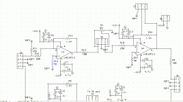
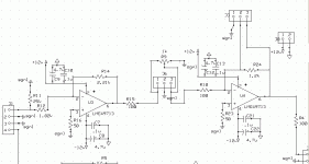
I got my inverted lme49713 pre amp working. The schematic is attached. It makes squarewaves out beyond the resolution of my scope! I have a few issues that I'm hoping you can help with. Each section of the amp runs at very low distortion, but when connected together - one op amp feeding the next, even with a fixed resistor instead of a pot, the distortion is higher. I'll post several images. First the schematic - note that in lieu of the pot I used a 604ohm resistor and left the ground open where the pot would connect in.
I got my inverted lme49713 pre amp working. The schematic is attached. It makes squarewaves out beyond the resolution of my scope! I have a few issues that I'm hoping you can help with. Each section of the amp runs at very low distortion, but when connected together - one op amp feeding the next, even with a fixed resistor instead of a pot, the distortion is higher. I'll post several images. First the schematic - note that in lieu of the pot I used a 604ohm resistor and left the ground open where the pot would connect in.
Attachments
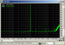
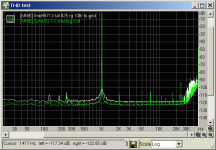
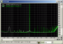
Here's the THD plot comparing the front end with the total amp as shown in the schematic. Note that the second op amp in series when measured by it's self has similar THD measurements to the first when measured alone. Do you have any thoughts? Is the first op amp struggling driving the second? I'll try to measure it while driving the second op amp tomorrow.
Thanks
Ken
Thanks
Ken
Attachments
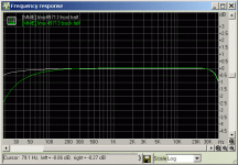
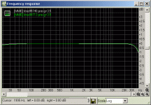
The second part is that the bandwidth of the second op amp is off in the lower frequencies. The only thing different about it's layout on the board is length of the ground traces - longer for the second op amp. Could this be causing this anomoly? Or is it just a measurement artifact?
Thanks
Ken
Thanks
Ken
Attachments
I changed a couple of things... I wasn't using a pot, just fixed resistors and had left the ground open where the pot would go. I put a resistor between 1 and 2 on J6 and things got much better. Then I went out and found a 1k pot and installed it. It behaved the same as the aforementioned resistor between 1 and 2. But, the second stage still had the low frequency fall off. I tried several different combinations without success. Then I decided that the front end might have to much gain. Gain was around 3.5 (2v in yield 7v out). So, I change the first stage gain setting resistor and the feedback resistor. I went with 2.21k Rf and 1.82k Rg. The THD is down to the sound card threshold and the frequency response is just a tick down at 30hz.
Revised schematic attached. Graphs to follow.
Revised schematic attached. Graphs to follow.
Attachments
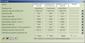
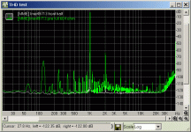
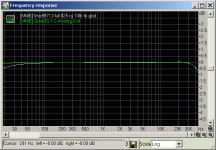
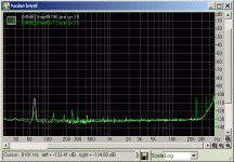
I think I posted the wrong image... I went back out to the shop and fired up my lme49740 to compare the low frequency and came up with this. I carefully set the gain with the scope so that each could be hooked up to the sound card without adjustments to the sound card settings. I found all the elments to be quite close between the two except for the square wave test. At 20khz the 49740 is rounding off the wave (and the signal generator overshoot) and has visible slew - the 49713 isn't slewing and it's showing the same overshoot as the signal generator.
The low frequency roll off is virtually gone with the tweaks mentioned in the prior posts.
The low frequency roll off is virtually gone with the tweaks mentioned in the prior posts.
Attachments
klewis said:The noise levels are almost identical except in the 60hz region, where the 49740 is worse than the 49713 - they both have 0.1uf ceramic caps at their power pins, but the 49713 also has 4.7uf tant caps at the pins as well.
60Hz spike is probably due to layout, earthing, shielding, wiring dress, power supply design.... not the chips themselves.
AudioX said:@Audioman54,
The LME49720 and LM4562 are the same parts?
You have said this and others have also stated as much including National support.
I am wondering why some say they seem to sound different when used in the same circuit?
Perhaps it's the weight of the extra ink on the product markings
I believe that Mark has (had) been pretty emphatic that the TO-99 versions are superior sounding.
LM4562HA input impedance
Hi guys,
Does anyone know what is the input impedance for the LM4562? I will be using it as a unity buffer after the Lightspeed attenuator before the cross-over. The Lightspeed attenuator prefer a input of 50k or more. If not, how do I increase it?
Thanks
Hi guys,
Does anyone know what is the input impedance for the LM4562? I will be using it as a unity buffer after the Lightspeed attenuator before the cross-over. The Lightspeed attenuator prefer a input of 50k or more. If not, how do I increase it?
Thanks
Re: LM4562HA input impedance
If you use it as a unity gain buffer, the input impedance will be much much higher than 50k. There should be no need to decrease it; even the lightspeed would like as light a load as possible.
jd
daredevil_kk said:Hi guys,
Does anyone know what is the input impedance for the LM4562? I will be using it as a unity buffer after the Lightspeed attenuator before the cross-over. The Lightspeed attenuator prefer a input of 50k or more. If not, how do I increase it?
Thanks
If you use it as a unity gain buffer, the input impedance will be much much higher than 50k. There should be no need to decrease it; even the lightspeed would like as light a load as possible.
jd
- Status
- This old topic is closed. If you want to reopen this topic, contact a moderator using the "Report Post" button.
- Home
- Amplifiers
- Solid State
- National opamp inflation
