KK,
I have some thoughts as to why the inverting circuits usually are better but of course there are always exceptions depending on circuit needs. I did just send Bob P an email asking for his thoughts on the subject and will post those as soon as I get them. As to the resistor values it depends on the circuit and input/output voltages. As Mr Pease says...build it and find out! (Just use the less expensive plastic parts first! Those metal can HA parts are way to expensive to blow up!)
Rocket Scientist,
Thanks so much for the kind words but I don't feel I am at the level of the of the audio engineering legends you mentioned in your post. I have had the chance to speak face to face with with Bob Cordell a couple of times and he is as knowlegable as anyone I have met in the audio industry.
Mark / Audioman54
audioman54 said:KK,
I have some thoughts as to why the inverting circuits usually are better but of course there are always exceptions depending on circuit needs. I did just send Bob P an email asking for his thoughts on the subject and will post those as soon as I get them. As to the resistor values it depends on the circuit and input/output voltages. As Mr Pease says...build it and find out! (Just use the less expensive plastic parts first! Those metal can HA parts are way to expensive to blow up!)
Rocket Scientist,
Thanks so much for the kind words but I don't feel I am at the level of the of the audio engineering legends you mentioned in your post. I have had the chance to speak face to face with with Bob Cordell a couple of times and he is as knowlegable as anyone I have met in the audio industry.
Mark / Audioman54
Hi Mark,
Ususally inverting circuits are better because there is no common mode signal (that would move +Vin and -Vin up and down in unison). In a perfect amp, common mode signals have no impact on the output signal since an opamp only is supposed to amplify the DIFFERENCE between +Vin and -Vin. Sadly, we are still waiting for our first shipment of ideal opamps...
")
As to the resistor values, what is an important factor is that the opamp has to drive the resistors in the feedback network. If you have a 1k feedback resistor and a Vin/Vout difference of 10V the opamp has to drive 10mA signal just for the feedback, even with no load. So you it depends on the capability of the opamp and the signal levels. Lower resistors give lower noise, but it's a tradeoff.
jd
JD,
Great Post! Thanks for adding to the thread! The CMRR on the LM49713 is 87dB typ and for the LME49710 110 dB typ. So that is another factor as to why the 49713 is better in inverting mode thus avoiding the reduced CMRR over it's VFB brother in the LME series.
Also the CFB parts have reduced PSRR over the VFB parts and thus regulated supplies are more important with the CFB LME parts. Bob and I presented at AES on this subject last year. Not sure if that presentation can be accessed online?
In spite of the reduced PSRR and CMRR with the CFB parts I still prefer the sound quality of the LME49713 over the 710. The 713 does have lower noise 1.9nV/�ãHz vs 2.5nV/�ãHz for the LME49710 and a much higher slew rate but we are still not really sure what parameter/parameters in the CFB part is/are responsible for the "perceived" increased sound quality. These kinds of questions are what make audio fun!!!
Mail just arrived with my new CD copy of the "All Star Percussion Ensemble" from First Impression Music. This is my favorite test disk of all time (over 30 years!) and FIM just remastered it at 352.8kHz. I am going to go listen to it right now.
Mark / Audioman54
Mark / Audioman54
audioman54 said:[snip] Bob and I presented at AES on this subject last year. [snip]
I know....
Edit: I don't think that presentation is online. But I'll look for it.
jd
Attachments
JD,
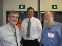
Nice pic...except for that strange looking guy in the middle!
Others have looked for it as well and have been unable to find it. I know AES taped it and it would be nice to have a copy of the tape.
And...
Wavebourn,
National decided a couple of years ago that Solar / energy efficient parts are the wave of the future. They have laid off 3500 employees remaking the company. But in the audio group (which is called something else now) were able to get those new LME parts made during a very small window of opportunity starting 5 years ago and I am very pleased that I was a part of that effort. The great news is National will keep making the LME parts (built on a great process) as long as we keep buying them!
Mark (they guy in the middle with the tie) / Audioman54
Hi Mark,
Let me first thank you for your contributions here. They are very much appreciated.
I have a current need for a good "direct box". I've been kicking around some ideas and would like to solicit your opinion. The problem is basically interfacing a bass guitar to a high end Yamaha digital mixer over 200-300 feet of Belden 9451. Most of the commercial direct boxes are either cheap and crummy or expensive (>$600) and meant for recording studio use where the cable runs are < 50ft. There will be an assortment of bass guitars to interface. Some are passive with an output impedance as high as 500K and some have active outputs.
I have been thinking of using a JFET follower (2SK170 ala Firstwatt B1 - see the Passlabs forum for more info on this) into an LME49724 and using the demo board circuit from the data sheet with single ended in and balanced out. The JFET is there to get a very high input impedance and I will use switchable resistors to match the output impedance of each guitar. The lowest frequency to pass is 31Hz.
Do you see a better solution from this IC line? Would adding the 49600 to the two outputs be worth doing? I am trying to avoid using a transformer due to cost.
Thank you for your help and good luck on your job search. Been there - done that. And I look forward to seeing you (employed) at BA.
Cheers,
Graeme
audioman54 said:
Wonder if I will have a job by then?
Good luck Mark!
It took me some hard time to understand that networking software hi-tech was over, and to accept the truth...
Graeme,
Is this a digital interface (S/P-DIF or AES-EBU)? Or an analog one?
(single ended or balanced 600 ohm).
I don't know anything about bass guitars at all. What is the usual output impedance, or output circuit, of a bass guitar? I need to know that before I can help. Generally driving long lines is best with a low impedance, 600 ohm, balanced line. Or a very low impedance single ended line.
Mark / Audioman54
Mark;
do you know if silicone carbide devices will be available soon, for solar energy applications? They promise to save an energy when switching, but in terms of linearity they should be better as well. By the way, it was the first semiconductor used on the Earth for radio, even before vacuum tubes.
Graeme;
no need to switch an input impedance, just make a headroom for active guitars. For driving, you may assume 100 picofarad per meter of cable pair. 600 Ohm was a standard power matching impedance long time ago, but now inputs in consoles have about 10K or higher input impedance (shunted by 6.81K resistors when phantom power is on). You have to deal almost with a cable capacitance only.
Hi Mark,
Thank you for the response.
This is analog audio. A passive electric bass guitar likes to see an impedance that is quite high - like 250K to 500K ohms or more. An active bass has a battery powered on-board preamp that is usually IC based and is AC coupled to the outside world. Both passive and active types of instruments are single ended out and neither has very much drive capability.
You can consider a passive electric or electric bass guitar to be akin to a dynamic microphone and an active output instrument to be akin to an ipod - give or take.
The job of a direct box is to take the low current input (of whatever impedance) and convert it to a high current 600 ohm line drive. Direct boxes have various gains from -30db to +12 db or more. I'm just interested in a solution that is in the unity gain to +6 ballpark.
The input to the mixer is 600 ohm balanced and the 9451 cable is shielded balanced twisted pair. I don't know what the capacitance of this cable is for sure but recall that it's roughly 27pf per ft between the inner conductors.
Graeme
Wavebourn said:do you know if silicone carbide devices will be available soon, for solar energy applications? They promise to save an energy when switching, but in terms of linearity they should be better as well. By the way, it was the first semiconductor used on the Earth for radio, even before vacuum tubes.
I have just started shipping product using the Silicon Carbide power
JFETs from SemiSouth. In linear circuits I'm getting much greater
linearity than Mosfets, with distortion as much as 1/10 in Class A
applications.
Nelson Pass said:
I have just started shipping product using the Silicon Carbide power
JFETs from SemiSouth. In linear circuits I'm getting much greater
linearity than Mosfets, with distortion as much as 1/10 in Class A
applications.
Wow!

I'm younger, but you are faster!

I go fishing now... Thanks for the info Nelson! How expensive they are compared to silicone MOSFETs?
Nelson Pass said:How about a sample unit price of $60 for the big one and $30 or so
for the small one?
I have factored that into the price of the First Watt J2.
Is http://www.semisouth.com/products/uploads/DS_SJEP120R063_rev1.3.1.pdf big one, or small one?
And how much is production if samples are so expensive?
- Status
- This old topic is closed. If you want to reopen this topic, contact a moderator using the "Report Post" button.
- Home
- Amplifiers
- Solid State
- National opamp inflation