inductance reduction is significant ?
One way to test it is to delete a trace on a PCB from driver to output and replace it with a wire of any length.
using copper pads for their wafers
You mean the connections from the wafer itself are soldered to pads.
Or a "die" is on a copper pad for better thermal conductivity?
But what does it tell us ?
Traderbam, do you also experience some uncomfortable moments with your regulated naim amp ?

But as you said before, placing drivers on separate heatsinks is a good idea, it has something to do with the distortion, i don't understand it completely. Everything depends on what case material is used, how fast is the heat removed from the case.
Legion used 2 ventilators in the case, that approach is good when drivers are affected by it.
But again, heat will be removed un-evenly from diodes and passive components too, so there might come in some distortion of somekind.
We need measurements, real-time...
Last edited:
On the theme of faster drivers etc., there are still many fast Japanese drivers and some reasonable copies of them that are cheap and could also be used in NAP/Nait series designs. FWIW, H140 kits were supplied with 2SD669/2SB649 drivers for some years.
The smaller 2SD667/2SB647 pair were often supplied as the VAS transistors in NAP140 kits too but they didn't sound as good as the original semis in the original model. Like BD139/140 and BC639/640, the 669/667 and 649/647 types are the same or similar silicon in different packages.
I picked these model transitors because you can buy them in reputable, marked brands like Unisonic and Wing Shing rather than unbranded, unqualified stuff that could be almost anything and any datasheets will be virtually useless. The good brands are usually stocked by Profusion and other spare parts distros in Europe. Have a look at their catalogue here: Transistors (Buy Online) | Profusion
This.Or a "die" is on a copper pad for better thermal conductivity?
It tells me that they made a big effort to use fast output transistors.But what does it tell us ?
I’m not using a Naim amp. I do have experience listening to Naim systems and I have experience of the Naim design.Traderbam, do you also experience some uncomfortable moments with your regulated naim amp ?
Hi guys
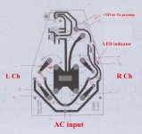
I received my boards from Jim's audio, very nicely done. As far as I saw compared to this site Modifying Naim Audio power amplifiers and what Jim's audio write in the description, the power supply board is an exact copy from the original.
Is is correct that I need a DC voltage of about 34V ? (in the clone schematics they mention 40V).
What I am not sure about is the transformer: According to the schematics I got there is a single winding with 0-24V and the Transfomer should be of about 160-200VA. No center Tap... is this correct ? I am confused after reading...
Thanks
Christoph
Attachments
Hi,
AC inputs are both ends of the secondary windings and the centre tap connects to ground. You can't run this amp without +/- DC rails.
Above 30V and below 40V per rail I think should work fine. I would suggest a bigger transformer, especially if you run close to +/-40V. Better >300VA.
AC inputs are both ends of the secondary windings and the centre tap connects to ground. You can't run this amp without +/- DC rails.
Above 30V and below 40V per rail I think should work fine. I would suggest a bigger transformer, especially if you run close to +/-40V. Better >300VA.
Last edited:
Yes, the rail voltages specified and found on larger NAP model amplifiers, is +/-40VDC which, for unregulated power supply models, suggests transformers with 2 secondary windings of 28VAC (it would be custom wound for this unusual voltage). Naim look-alike 110/220VAC mains supply transformers of about 350VA rating and 28V secondary windings can be sourced from China but freight costs are a problem there.
Clones of the smaller NAP140 model require about +/-34VDC supplies and can work with standard, dual 25VAC secondary windings on even a 160VA rated transformer, as long as it doesn't have to drive 4R speakers at maximum bass volume or some such high power level.
Clones of the smaller NAP140 model require about +/-34VDC supplies and can work with standard, dual 25VAC secondary windings on even a 160VA rated transformer, as long as it doesn't have to drive 4R speakers at maximum bass volume or some such high power level.
Last edited:
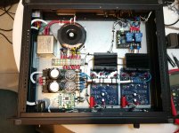
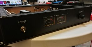
Here is my clone amp...
i love viewing all of your posts. great job.
i started this project about 1 year ago. it took a lot of time to complete.
the input capacitors where changed to foil.
i have some line voltage filtering.
the amp is built inside 2U rack enclosure i found 10 years ago and kept.
the heat sinks are from a LPKF CNC old motor driver board. (i converted it to mach3).
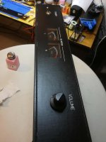
i used the CNC to cut the panels and text.
the volume pot is ALPS (ali express version).
i love viewing all of your posts. great job.
i started this project about 1 year ago. it took a lot of time to complete.
the input capacitors where changed to foil.
i have some line voltage filtering.
the amp is built inside 2U rack enclosure i found 10 years ago and kept.
the heat sinks are from a LPKF CNC old motor driver board. (i converted it to mach3).
i used the CNC to cut the panels and text.
the volume pot is ALPS (ali express version).
An externally hosted image should be here but it was not working when we last tested it.
An externally hosted image should be here but it was not working when we last tested it.
An externally hosted image should be here but it was not working when we last tested it.
An externally hosted image should be here but it was not working when we last tested it.
Yes, some very tidy and pro. quality assembly work there. Some nice tools you have too!
However, you won't be able to listen at high volume for long without the output transistors overheating. For normal convection cooling, as I see it, those heatsinks are way too small, the fin spacing too narrow and wrongly aligned. Unless you also have fan-forced air draughts for those sinks, let me suggest some basics for normal convection cooling:
- Heatsink Fins should be aligned vertically to allow air to flow freely from one end of the fins to the other.
- There should be vents in the case to admit cool air at the bottom and exhaust hot at the top, usually directly above and below the heatsink.
- Fin spacing and thickness should be large - typically spaced with 10mm pitch and the thermal rating should, I think, be at most 1.5K/W for each NAP 140 amplifier module, assuming no more than standard +/-34-35 VDC power supplies).
Your current heatsinks will be rated for use with a specific fan and duct/cover but it is unlikely the present arrangement will stay reasonably cool with more than a few watts output, even though only a small bias current is used.
Heatsinks don't need to be huge for the power levels used in most homes and apartments (i.e. <5W) but with those little fan-forced air types, you wont be able to listen at living room levels (and definitely not party levels) for long before there is a smell of hot transistors, burning and then silence. You could add a simple thermal power switch to avert such a disaster but that's hardly a solution.
i love viewing all of your posts. great job.
i started this project about 1 year ago. it took a lot of time to complete.
the input capacitors where changed to foil.
i have some line voltage filtering.
the amp is built inside 2U rack enclosure i found 10 years ago and kept.
the heat sinks are from a LPKF CNC old motor driver board. (i converted it to mach3).
i used the CNC to cut the panels and text.
the volume pot is ALPS (ali express version).
I would like to join in the compliments on the cleanliness and the general great accuracy of workmanship.
Excellent LC cell power supply filtering, softstart circuit and DC output voltage protection.
But apart from perhaps the small size of the toroidal power transformer, I have to agree with Ian Finch:........ the two heatsinks are unacceptably small, and the position of the power transistors, with respect to the radiating mass, should never be peripheral but always central and barycentric to maximise heat loss and reduce Thermal Resistance.
I would see the following modifications as perfect, in priority order:
1) Replacement of the heat sinks,
2) Increase the power of the toroidal power transformer,
3) Adding a pair of electrolytic filtering capacitors for improved dynamic performance of the amplifier.
Just to provide an element of comparison, the one in the picture below is one of my versions of the NAP-140 Clone with a 600 VA - +/- 29 Vac toroidal transformer and a 3.5 kg radiant mass, which can be seen at the top right of the picture, under which are installed the two amplification boards and even two thermostat-activated fans (45 degrees Celsius) which in reality intervene only in prolonged listening at high volume or with demanding speakers with low characteristic impedance such as my Magnepan.
An externally hosted image should be here but it was not working when we last tested it.
An externally hosted image should be here but it was not working when we last tested it.
Last edited:
On the construction topic, I'd like to remind everyone still building a Naim clone, rather than something else, that the official looking old schematic you see everywhere on the 'net and most clones (including Avondale's) have been based on, is not the same as NAP140. It is actually the schematic for the amplifier section only of NAP250 and NAP135 which also had full, discrete component, regulated power supplies of +/- 40V. Regulation was necessary because of the the original power transistor SOA limits, such that they could safely deliver a full 70W and 75W per channel respectively to 8 Ohm loads. NAP140 is rated at just 45W/8 Ohms and its unregulated supplies are +/-35V unloaded.
The circuit remains much the same for all NAP models but it's in maintaining the same bias with different supply voltages that sound quality can be made more or less consistent from one model to another, whatever the DC supply voltages. Consequently, there are are minor differences in the bias current setting resistors for the front end LTP(1.5 mA) and VAS sections (12mA) respectively, which differ between early NAP models.
For more material, here's an interesting old reference article with plenty of details, comments and suggestions that are mostly out of date now, so follow the forum link at the bottom of the page for more recent suggestions. Modifying Naim Audio power amplifiers
good work and good pictures. Unfortunately URLs don't goes open without copy in a new browser window.i love viewing all of your posts. great job.
i started this project about 1 year ago. it took a lot of time to complete.
the input capacitors where changed to foil.
i have some line voltage filtering.
the amp is built inside 2U rack enclosure i found 10 years ago and kept.
the heat sinks are from a LPKF CNC old motor driver board. (i converted it to mach3).
i used the CNC to cut the panels and text.
the volume pot is ALPS (ali express version).
Additional at such portals like https_photos.app.goo.gl images are deleted after several months - this is a great disadvantage. Therefore it is better to upload here the images.
+1000000For more material, here's an interesting old reference article with plenty of details, comments and suggestions that are mostly out of date now, so follow the forum link at the bottom of the page for more recent suggestions. Modifying Naim Audio power amplifiers
Thank you all for all your comments and insight.
As for the heat sinks, they dont get hot at all... im using a 4 ohm speakers and even at high volume levels the heatsinks dont get hot. So much that i tought that i could have done without it and just couple the transistors to the chassis. Maybe i need to do real measurments of power and temperture.
As for the toroidal transformer bigger is better and more power bank capacitors are welcome.
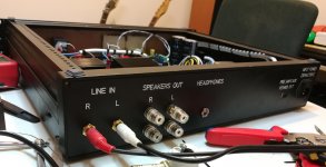
I connected 2 resistors to the outputs for a headphone jack. 470 ohm i think 3-5 watt.
I was somehow disappointed with the resolution and seperation compared to the phones output from the sound card umc404hd. It was brighter and had more details.
Maybe I should test with different value of resistors. Maybe its an impedance thing.?
Im using sony mdr7506 headphones.
As for the heat sinks, they dont get hot at all... im using a 4 ohm speakers and even at high volume levels the heatsinks dont get hot. So much that i tought that i could have done without it and just couple the transistors to the chassis. Maybe i need to do real measurments of power and temperture.
As for the toroidal transformer bigger is better and more power bank capacitors are welcome.
I connected 2 resistors to the outputs for a headphone jack. 470 ohm i think 3-5 watt.
I was somehow disappointed with the resolution and seperation compared to the phones output from the sound card umc404hd. It was brighter and had more details.
Maybe I should test with different value of resistors. Maybe its an impedance thing.?
Im using sony mdr7506 headphones.
its beautiful. great work
im not experiencing any temperature issues. the signal has no cross over distortion at all and the dc output voltage is extremely low on both channels when idle.
maybe some of you have the quiescent current set to high?
picture below is one of my versions of the NAP-140 Clone with a 600 VA - +/- 29 Vac toroidal transformer and a 3.5 kg radiant mass said:
im not experiencing any temperature issues. the signal has no cross over distortion at all and the dc output voltage is extremely low on both channels when idle.
maybe some of you have the quiescent current set to high?
thank you for the advice! im attaching the images.
good work and good pictures. Unfortunately URLs don't goes open without copy in a new browser window.
Additional at such portals like https_photos.app.goo.gl images are deleted after several months - this is a great disadvantage. Therefore it is better to upload here the images.
Attachments
- Home
- Amplifiers
- Solid State
- NAP-140 Clone Amp Kit on eBay