Hi,
I've used this circuit (42.5) for awhile, because I thought it would have been a good match with the 140 clone. It's a simple and very cheap preamp, nothing special. I didn't buy the kit, just made it on a prototype board. Will work fine and will have a pretty high gain, that you won't need with the 140 - about x10 if I recall correctly.
I switched to N. Pass preamps, though. The 42.5 changed the sound somewhat which is not my idea of a good preamp. I'd prefer to not hear the preamp in the system and the Pass ones are nearly perfect in this domain. This kit looks very well made, so it may be also better sounding than mine prototype.
Hi marcel5996,
Finally you found it. This explains your blowing protection resistor on the power supply line.
I think this amp will work normally at 2x47V. Capacitors are usually conservatively rated, so they will be fine. Transistors should have enough reserve in Vce. I try to use transistors rated at least twice the supply rail they are connected to. For example, for 2x47V I would look for transistors having Vce=100V minimum. I would do same with the capacitors but it's too expensive and bulky. The reason is that in extreme conditions, during failures of some components, some transistors may see the whole voltage across them. They are very easy to blow, even for fraction of a second of overvoltage.
I don't like regulated power supplies in amps, but it's just my biased opinion.
For separating the PS and the main boards: I would rectify the voltage close to the amp. Look at the national power grid shows that transporting AC is more common. I don't think it matters in audio, but anyway. Also, if you use the point between the capacitors as a star ground point (and you should), they have to be closer to the amp boards.
If you decide to transport 2xAC + center tap, I'd recommend using a cable having 3 conductors and a shielding. You can connect one side of the shield to one of the boxes (usually to the output box, in your case the box with the transformer inside). The shield is to prevent picking hi-frequency interference noise, cables are also sort of radio antennas. The transformers are intrinsically decent RMI filters, and you don't want RMI picked again after your transformer. If you need better power line noise suppression then you should use an isolation transformer and to connect your whole audio system after. I found this better solution than any EMI/RMI passive filters etc., but I've never tried AC regeneration devices which are very expensive.
Hope this may help.
Regards
Hi marcel5996,
Finally you found it. This explains your blowing protection resistor on the power supply line.
I think this amp will work normally at 2x47V. Capacitors are usually conservatively rated, so they will be fine. Transistors should have enough reserve in Vce. I try to use transistors rated at least twice the supply rail they are connected to. For example, for 2x47V I would look for transistors having Vce=100V minimum. I would do same with the capacitors but it's too expensive and bulky. The reason is that in extreme conditions, during failures of some components, some transistors may see the whole voltage across them. They are very easy to blow, even for fraction of a second of overvoltage.
I don't like regulated power supplies in amps, but it's just my biased opinion.
For separating the PS and the main boards: I would rectify the voltage close to the amp. Look at the national power grid shows that transporting AC is more common. I don't think it matters in audio, but anyway. Also, if you use the point between the capacitors as a star ground point (and you should), they have to be closer to the amp boards.
If you decide to transport 2xAC + center tap, I'd recommend using a cable having 3 conductors and a shielding. You can connect one side of the shield to one of the boxes (usually to the output box, in your case the box with the transformer inside). The shield is to prevent picking hi-frequency interference noise, cables are also sort of radio antennas. The transformers are intrinsically decent RMI filters, and you don't want RMI picked again after your transformer. If you need better power line noise suppression then you should use an isolation transformer and to connect your whole audio system after. I found this better solution than any EMI/RMI passive filters etc., but I've never tried AC regeneration devices which are very expensive.
Hope this may help.
Regards
Hi Ruwe thanks again for your help. I checked all trannies, they are ZTX753, MJE15033/32 (drivers), MJL3281 (output), MPSA56/056 and BC550. With the exception of the BC550 they're Vce rated at 80-100 V. I will change the BC550 for BC546, to be on the safe side (or maybe SC2240, which has a different pin layout though). As to the external PSU, was thinking of keeping the caps close to the amp board (for the ground star) and the rectifiers with the toroid in the PSU case. The umbilical would then transport raw DC. Any thoughts? I'm quite confused on the grounding though. My toroid is dual secondaries (not centertapped) with two bridge rectifiers. In this case I would use a 4 core cable + shield. The mains earth should be in the PSU case, but then how do I ground the amp case to the mains earth? Shouldn't the shield in the umbilical cord be connected to both cases in order to ground the amp case? The ground point across the caps needs be connected to mains earth, to do this the amp case has to be grounded to mains earth earth, am I right? Finally, I will keep the umbilical very short (~50 cm), is 5 pin din connection the recommended way to go (I think these are only rated 35 VDC though and accept 22 gauge wire only), or the neutrik speakon (but I think they are for speakers and have 4 poles max). Sorry for the length, I'm finally sorting things out, a piece at a time
")
Hi,
You can transport DC or AC. I don't think it matters very much, especially for 50 cm. Just a matter of ease to apply.
Yes, if you use two secondaries and dual rectifier, then use 4 wire + shield if you can find such a cable. There should be some on the electrical market. Or use 2 cables, one for each rectifier.
If you don't have any other way to ground the case of the amp you can definitely use the shield to transfer the earthing between the boxes. Just find a cable with good thick shielding. As about earthing the star ground, you should experiment. You may find that it's not necessary, especially if you have earthing elsewhere in the signal path.
I wouldn't recommend DIN connectors. Use XLR connectors instead. There are many types and I've seen for sure a 4-pin one. XLRs are sturdier than DINs, I've read they are used in lighting installations and can handle 10A (Wikipedia). I am fan of XLRs! You don't need to buy anything expensive Neutrik-like. I personally bought for my Aleph1.7 pre some Chinese XLRs. They are locking together and are very well built for about 3-5$/ea, depending on the type - case mount or for cable. Contact-wise are much better than DINs.
There is also a XLR standard for inputs and outputs, so you can check before, if you want to be compliant Although, I'm not sure there is any rule for non-standard voltage transfer, so you can use whatever combination you like or can fit as male-female pair.
Regards
You can transport DC or AC. I don't think it matters very much, especially for 50 cm. Just a matter of ease to apply.
Yes, if you use two secondaries and dual rectifier, then use 4 wire + shield if you can find such a cable. There should be some on the electrical market. Or use 2 cables, one for each rectifier.
If you don't have any other way to ground the case of the amp you can definitely use the shield to transfer the earthing between the boxes. Just find a cable with good thick shielding. As about earthing the star ground, you should experiment. You may find that it's not necessary, especially if you have earthing elsewhere in the signal path.
I wouldn't recommend DIN connectors. Use XLR connectors instead. There are many types and I've seen for sure a 4-pin one. XLRs are sturdier than DINs, I've read they are used in lighting installations and can handle 10A (Wikipedia). I am fan of XLRs! You don't need to buy anything expensive Neutrik-like. I personally bought for my Aleph1.7 pre some Chinese XLRs. They are locking together and are very well built for about 3-5$/ea, depending on the type - case mount or for cable. Contact-wise are much better than DINs.
There is also a XLR standard for inputs and outputs, so you can check before, if you want to be compliant
Although, I'm not sure there is any rule for non-standard voltage transfer, so you can use whatever combination you like or can fit as male-female pair.Regards
I just want to report back some results.
I have completed building one channel of this amp and have succesfully run it through a series of measurements using signal generator and cro.
First up the only changes I made was to replace the input transistors to 2sc2240 and the output transistors to mjl4281. With this setup the amp ran beaurifully.
I then decided to change the drivers from tip41c/42c to 2sa1837 and 2sc4793, however with these I got oscillation.
My next variation (when the parts arrive) will be 2sc5171 and 2sa1930.
So if you have used 2sc4793 and 2sa1837 as driver transistors and the amp does not sound so good then you probably have oscillation ocurring.
Last edited:
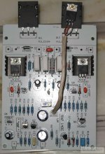
Here is a link to some photos of the same kit I received:
NAP140×°»úÈÕ¼Ç - ÒôÏìDIYÂÛ̳ - HIFIDIYÂÛ̳ - Powered by Discuz!
i think this amp have a design wrong.
it is do not work in class ab .because it has no thermal compensation.
this is a very problem ,will lead output transistor to damage.
i was diy NAP140 but i think that performance is not good than my design :mx50
Attachments
Last edited:
ok i fixed the power supply problem , connected now in the right way - I have 41 Volts now.
Power Transistors still not in. When i switch on the 100 Ohms Resistors around the Power Transistors start to smoke. Please help me
You can use 1N4001 or any silicon diode to replace the 2sc5200 Base and Emitter (check the direction when soldering the diode), then you can power up and see what is going on without the possibility of damaging 2sc5200. 2sc5200 is about $2 each. Expensive!
With diode replacing 2sc5200, there is no current gain for NAP-140 but there is voltage gain. As long as you don't connect to low impedence load (such as speaker), you can do all of the checking with multi meter.
When power up,
0. Watch for smoke or any device which is hot for your finger. This indicates that something is still wrong. Need to power down ASAP if you see any sign of trouble.
1. You can check the output voltage with DC meter, it should be small (< 100mV)
2. With a small signal as input, the AC multimeter should indicating some output voltage (1V AC maybe)
3. You can check the vltage across Q5 Vce. By adjusting the trim pot, voltage should change at least between 1.4V - 2.4V.
4. Make sure the trim pot set to lowest Q5 Vce voltage so that no huge current will go through 2sc5200 when connected later on.
5. And good luck when power up
One more thing I forget to mention.
Q5 is responsible for biasing those 4 transistors.
These 4 transistors are bipolar structure and has positive temperature cofficient.
(Meaning when they are hot, Vce will drop and more current wil go through.
And more current go through result in higher temperature, then much more current go through .... This will cause thermal breakdown)
Need to attach Q5 to heat sink. When heat sink temperature rise, Q5 Vce will drop, that reduce the bias across those 4 transistor. And result in lower current go through these 4 transistors.
I don't know where you place the Q5 ?
You can leave Q5 on the board for debug until you are ready to crank up the current and let NAP-140 running for hours.
If you have oriented correctly all transistors and BOTH resistors are getting hot, then just turn the trimmer maximum CCW. This should reduce the current through Q9 and Q10 to minimum.
If resistors are still hot, check Q5.
You should measure something like 2.2-2.5V between the bases of Q9 and Q10, I assume you must have much more now. What's the voltage across each 100ohms resistor?
If resistors are still hot, check Q5.
You should measure something like 2.2-2.5V between the bases of Q9 and Q10, I assume you must have much more now. What's the voltage across each 100ohms resistor?
Last edited:
Hum
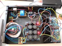
Problem with hum. This is my nap140 clone layout. The sound is ok but i found little hum. Any suggestion about wiring and grounding. I don't know how to ground it correctly.
Thanks.
Problem with hum. This is my nap140 clone layout. The sound is ok but i found little hum. Any suggestion about wiring and grounding. I don't know how to ground it correctly.
Thanks.
An externally hosted image should be here but it was not working when we last tested it.
Attachments
- Home
- Amplifiers
- Solid State
- NAP-140 Clone Amp Kit on eBay