thanh1973 said:I think you can use BC546 instead of BC550 which is rated for a higher voltage (ie 80V)
I used 2sc2240, but I had to twist the legs around. No big deal realy.
Thanks! I solved the problem by replacing new transformers (2x monoblock)

By modern standard, this amp is noisy. Is there audible noise improvement using 2sc2240?
Cheers!
C
Re: Nap 140-C Amp clone
I supposed that you did a good check at Q5? The transistor outline is wrong...
marcel5996 said:Hi all, I'm a newbie who got "bit by the bug". Enjoyed so much this thread that decided to purchase Nap 140-C clone bare boards on ebay (the longer ones) and build my first amp. Parts were selected separately picking from this thread suggestions. Did my homework studying and reading carefully other diyers' experiences on this thread. I'm at my third board and still can't get it to work!! Was hoping someone could help me troubleshoot, maybe posting some of the approximate readings that I should expect at the different stages. I have a 250 VA 30-0-30 toroid, dual rectification with 8x4700uf (4 each rail) smoothing caps. Don't have variable bench power so I set lamp bulb in series with mains (only lights up briefly at power up), have 2x10 ohm 10 watt resistor at main supply and 2x100ohm at +/- pcb supply terminals to make sure I get warned if there is a short. Input ground, speaker, pcb ground all go to the common point on the caps. With no input/no output load everything seems fine at power up, current set to suggested minimum of 10ma (2.2mv across emitter resistor r29), negative rail showing the same reading. Output DC offset around 12mv, trimpot works, resistance across r17 is around 650ohm. All transistors/caps checked for proper forward bias and correct alignment. Have MJL3281A output transistors mated with MJE15032/3 drivers (as per Neil McBride). What happens is that when I finally attach a speaker (no input yet), the "warning" 100ohm resistor on the negative supply side overheats with smoke, forcing me to power off (no time to check music). Also tried with quiescent current set at minimum level, 1.4mv across r29, or 6.4ma (275mv across base/emitter 100ohm resistor r26) which should give hardly no current at all to power transistor with the same result. Any idea what is going on? Thank you very much for any help/suggestion.
I supposed that you did a good check at Q5? The transistor outline is wrong...
Re: Re: Nap 140-C Amp clone
Hi skyraider, thanks. Yes, after reading the posts on wrong transistors outline I double checked all transistors with boards schematics.
skyraider said:
I supposed that you did a good check at Q5? The transistor outline is wrong...
Hi skyraider, thanks. Yes, after reading the posts on wrong transistors outline I double checked all transistors with boards schematics.
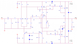
DreadPirate said:I compared this schematic with the one posted by Carlos, some slightly different values, those are highlighted with an asterisk.
Sorry to revive a rather old thread - but I bought this same kit about a year ago (maybe 18 months!) and have just got around to looking at building it.
I wasn't supplied with a schematic, and I was happy to find the copy you had posted. Mine differs slightly ffrom yours, in that it has two additional components in the feedback loop.
My board also has all component values on the silk screen layer.
I preapred the attached schematic, based on your poseted schematic, and comparing that with my PCB.
Tony.
EDIT: I can't seem to get the schematic clear here..
EDIT: Embed image.

Attachments
I've also noticed some people have been having problems with the transistor orientation.
I scanned the silk screen side of the board, and marked out (in orange text) the Base / Emitter and Collector pins.
This hopefully will help others who might be constructing this kit.
All the transistors supplied with my kit appear to be exact matches for the layout.

I scanned the silk screen side of the board, and marked out (in orange text) the Base / Emitter and Collector pins.
This hopefully will help others who might be constructing this kit.
All the transistors supplied with my kit appear to be exact matches for the layout.
Hi marcel5996
I may be a little late, I don't read the forum very often, but the first thing to check is where you attach your speaker. Of what you're saying it looks to me that you have connected the speaker between the negative power rail of your board and the ground (or from negative power rail and the speaker output). This way you're shorting through the speaker the negative rail.
If your amp is stable without load then your load is the problem. Check where are your terminals attached on board.
audio_tony said:
I preapred the attached schematic, based on your poseted schematic, and comparing that with my PCB.
Hi Tony
I think there is a small error in your schematic. The upper driver base is connected through a 470pF capacitor only. Probably this network has to be the same as for the lower driver. I hope the PCB is Ok.
Hans
807 said:
Hi Tony
I think there is a small error in your schematic. The upper driver base is connected through a 470pF capacitor only. Probably this network has to be the same as for the lower driver. I hope the PCB is Ok.
Hans
Hans, Indeed there is an error with my schematic!
Well spotted - the upper network should be the same as the lower of course.
The PCB as supplied is correct - that was just my mistake.
I will correct it and repost the correct schematic.
Thanks,
Tony.
EDIT: The correct schematic is now displayed in the post above. The attached schematic is still wrong however - I could not edit that.
I built both boards today - my next steps are to construct a suitable chassis - and then test...
Taking stock of the various NAP 140 clones
I’m trying to understand the merits of the various NAP 140 clone kits and pcbs. From what I can determine there are at least four or 5 of these:
• Gigaworks kit (NAP 140/Avondale) design
• Tubeshunter kit -NAP140c
• Diyhifi.net (NAP 140-same board as tubeshunter?)
• Jim’s Audio Red NAP pcb
• Avondale NCC200
Forum members have posted their experiences on their technical and musical success or otherwise in building NAP 140 clones but it is often not clear which specific “variant” they are referring to. Also there a references to errors on pcb overlay and the need to change the quality of various components.
I was wondering if, as a result of this collective experience, there was some general consensus on which particular kit variant (after tweaking components and correcting errors in kits) was the best way forward-both technically and musically- and how well the best of these variants compares with the real thing?
Hi
I have built the tubeshunter nap140c kit and it works perfectly with no changes to the circuit, such as orientation problems etc.
the only problem I had was i could not seem to measure the voltage across the emitter resistors when setting up the quiescent current.
Other than that I would recommend without hesitation - I will probably buy another pair in the near future.
I am also really pleased with the sound, easily as good as my old Roksan Kandy (probably better actually !)
Graham
http://209.85.227.132/translate_c?hl=en&sl=zh-CN&u=http://www.hifidiy.net/jhwz/200707/t20070720_1194.htm&prev=/search%3Fq%3Dhifidiy.net%2Bnap%2B140%26hl%3Den%26sa%3DG&rurl=translate.google.co.uk&usg=ALkJrhie4mENawCEpBkgvBBR67uErQylHg
Might be of some use? I got the diyhifi version, Havent started it yet, but it looks OK quality wise.
Might be of some use? I got the diyhifi version, Havent started it yet, but it looks OK quality wise.
Re: Taking stock of the various NAP 140 clones
I bought my kit from Tubeshunter - and the boards I received are marked Diyhifi.net - so I'm guessing it's safe to say they are from the same source.
I've also noticed that snow48_6 and gigawork seem to be selling **very** similar DAC boards on eBay (are these possibly from the same source too?)
Tony.
pattox said:I’m trying to understand the merits of the various NAP 140 clone kits and pcbs. From what I can determine there are at least four or 5 of these:
• Gigaworks kit (NAP 140/Avondale) design
• Tubeshunter kit -NAP140c
• Diyhifi.net (NAP 140-same board as tubeshunter?)
• Jim’s Audio Red NAP pcb
• Avondale NCC200
Forum members have posted their experiences on their technical and musical success or otherwise in building NAP 140 clones but it is often not clear which specific “variant” they are referring to. Also there a references to errors on pcb overlay and the need to change the quality of various components.
I was wondering if, as a result of this collective experience, there was some general consensus on which particular kit variant (after tweaking components and correcting errors in kits) was the best way forward-both technically and musically- and how well the best of these variants compares with the real thing?
I bought my kit from Tubeshunter - and the boards I received are marked Diyhifi.net - so I'm guessing it's safe to say they are from the same source.
I've also noticed that snow48_6 and gigawork seem to be selling **very** similar DAC boards on eBay (are these possibly from the same source too?)
Tony.
graham-r said:Hi
I have built the tubeshunter nap140c kit and it works perfectly with no changes to the circuit, such as orientation problems etc.
the only problem I had was i could not seem to measure the voltage across the emitter resistors when setting up the quiescent current.
Other than that I would recommend without hesitation - I will probably buy another pair in the near future.
I am also really pleased with the sound, easily as good as my old Roksan Kandy (probably better actually !)
Graham
Based on my own experience, and the quality of the supplied kit, I'm anticipating mine too will work without any issues.
Tony.
There certainly appear to be two main variants of the Chinese supplied boards, referred to by some as the "long and thin" and the "short and fat". It appears from my ploughing through the threads that MOST of the board labelling errors seem to apply to the "long and thin" versions; most of the "short and fat" boards, like the gigaworks ones, do not seem to be incorrect in this respect.
I note that most of these boards appear at various times on www.taobao.com, which is worth a look, as is diydiy.net for one of the suppliers selling on taobao.
The "short and fat" boards are discussed at length in the following thread, which also provides PCB overlay files and layouts (and clearly shows how the boards are copies of the avondale circuit):
http://bbs.hifidiy.net/viewthread.php?tid=48492&extra=&page=1
in particular:
http://bbs.hifidiy.net/viewthread.php?tid=48492&extra=&page=2
You will note that the pdf file links on page 2 of the thread cause added confusion in that ALL all the capacitor and transistor numbers are different from the gigaworks ones, yet clearly the boards are derived from the same master layout which is attached in one of the posts...
My own boards (yet to be built) were bought in China from taobao before I knew about the above, and these are clearly similar to the gigaworks kit [but at a fraction of the price ]. However instead of 2 off 2705 transistors there's a 2705 and a 2240, so it is an interesting challenge to find which should be fitted where.......
Just my tuppence worth....
I note that most of these boards appear at various times on www.taobao.com, which is worth a look, as is diydiy.net for one of the suppliers selling on taobao.
The "short and fat" boards are discussed at length in the following thread, which also provides PCB overlay files and layouts (and clearly shows how the boards are copies of the avondale circuit):
http://bbs.hifidiy.net/viewthread.php?tid=48492&extra=&page=1
in particular:
http://bbs.hifidiy.net/viewthread.php?tid=48492&extra=&page=2
You will note that the pdf file links on page 2 of the thread cause added confusion in that ALL all the capacitor and transistor numbers are different from the gigaworks ones, yet clearly the boards are derived from the same master layout which is attached in one of the posts...
My own boards (yet to be built) were bought in China from taobao before I knew about the above, and these are clearly similar to the gigaworks kit [but at a fraction of the price
]. However instead of 2 off 2705 transistors there's a 2705 and a 2240, so it is an interesting challenge to find which should be fitted where.......Just my tuppence worth....
Re: Speaker Protection
There are several on Ebay.
Speaker Protection Modules on Ebay
Vellerman do a kit as well.
The world is your oyster, when you explore the "search" button!
DreadPirate said:Can someone suggest premade or kit speaker protection circuits that are apparently missing and needed from the original blue board design?
There are several on Ebay.
Speaker Protection Modules on Ebay
Vellerman do a kit as well.
The world is your oyster, when you explore the "search" button!
- Home
- Amplifiers
- Solid State
- NAP-140 Clone Amp Kit on eBay